Roughing End Mill

I will be building several copies of my “Aluminum Frame Reel” this winter, and I am beginning to think about quicker ways to move metal. At present I have 0.1 hp lathe and mill from Sherline. I think that the next step up would be the 0.5 hp lathe and mill from MicroMark. But these larger tools would not be suitable for use in my utility room at home; I would have build, heat, and air condition a real shop. For now I will stick with Sherline.

In a effort to work a little smarter with what I have, last week I bought a “roughing” end mill (Niagara Cutter EDP #75201, McMaster-Carr 3300A31). For end plates and spool ends, I start with a piece of rectangular bar stock and use the mill to roughly shape the part before moving to the lathe. If the roughing end mill lives up to its name, it should be a more efficient tool for this task.

This end mill was able to make groove cuts of .070 depth with little sign of load on the mill. I am sure that I could have made deeper cuts. Here it is rounding the corners of rectangular bar stock. Despite having 3 flutes, it did not chatter side-to-side when it got into the double sided area of the groove.

Where it cuts with its side, the part surface is indeed quite rough. But where it cuts with its end, the part surface looks as if cut by any end mill.

It plunges without hesitation, and so can form recesses. This is “center cutting” capability.

The reason that it can center cut is that one of the three flutes, on the end, has a cutting edge that goes all the way to the center.

In all, I am quite satisfied with this end mill and expect it to save me some time in preparing blanks for the lathe.

Update 16 Oct 2011: I have some difficulty plunging with general purpose end mills. I advance the z-axis leadscrew slowly but the headstock lowers in small jumps, shaking the whole mill with the sudden bite. It is rather unnerving. But this morning I particularly notice that the roughing end mill is much smoother for this operation.

Posted in Cutting, Milling | 1 Comment

Pawl Testing at Higher Speed

This is the seventh posting in this blog on durability testing of ratchet and pawl materials. Previous posting are:
1. Picture of tester based on a “gearmotor”, 25 rpm (30 May 2010)
2. First results from tester (22 Aug 2010)
3. Retraction of first results; “gearmotor” was unreliable (6 Sept 2010)
4. Retest results with 20 rpm gearmotor (16 Nov 2010)
5. Picture of higher speed gearmotor, 220 rpm (13 Apr 2011)
6. Add two more plastics to 20 prm results (7 May 2011)

So far the tests have concentrated on plastic materials. My first group of reels used Delrin pawls running on bronze ratchets. When I would run a metal pawl on metal ratchet, there would always be excessive wear, but I was using soft and easily machined metals. Another problem with metal pawls was that they were too loud.

I initiated some discussion of materials on Rod and Reel Maker’s Forum. Success with tool steel was reported. However, several factors have kept me from any work with tool steel:
1. The machinability index is very low – important when working with Sherline mill.
2. It would still be too loud.
3. It would have little corrosion resistance.

Seeking a more suitable steel, I have settled on 416 stainless. This is a free machining grade that can be hardened, and has about 13% chromium for improved corrosion resistance. It does not solve the sound level problem. Impact resistance is slightly higher than for A2 tool steel. I have made two sets of ratchets and pawls from 416; the first set was tempered at 700F. Because this temper could lead to “blue brittleness”, I did a second set at 600F. Two recent posts ( 8 and 17 Aug 2011) cover heat treatment.

In this post I report on results obtained with the higher speed gearmotor (220 rpm). It emphasizes impact over friction. Unlike the low speed tester, wear cannnot be easily measured, so I can only make qualitative observations.

Here is the 220 rpm tester, along with some of the test items. My standard test is to run a ratchet-pawl set for 15 hours, resulting in about 6 million impacts on the pawl. When I ran a Delrin pawl on a bronze ratchet, there was no significant damage to either. The Delrin pawl was marked on the flank where ratchet teeth strike, but there was insignificant material loss.

When I ran the first 416 stainless pawl on a bronze ratchet, much bronze debris was created, but there was little damage to the pawl.

When the first 416 pawl was run on the first 416 ratchet, the pawl was eroded (perhaps half of its useful life) but the ratchet appeared to be only polished.

Here is the second stainless pawl (600F temper) before testing. The hardness of this part is Rockwell C 43.

And here it is after a 15 hour run on the second stainless ratchet. The tip has lost material, but not as much as for the first stainless pawl. This suggests that the lower temperature temper may have helped.

I also ran Delrin pawl on Ertalyte ratchet, Ertalyte pawl on Delrin ratchet, and Delrin pawl on Delrin ratchet. The edges of the pawl tip and the ratchet teeth acquired a slightly grimy appearance, but there was no visible wear in any case.

Is pawl wear a problem? Apparently it can be. Here is a photo of a well-used Hardy “Green Princess”.

Photo courtesy of “jhcoffeebum”, used with permission.

I have decided that Delrin is the best choice of the materials that I have evaluated:
1. Lighweight
2. Widely available
3. Corrosion resistant
4. Easily machined
5. Superior wear characteristics
6. Relatively quiet.

Update 13 Oct 2011: It has just come to my attention that the material that I have been calling “Delrin” is actually acetal copolymer. There is a minor difference, read here.

Update 3 Nov 2011: Swedish reel maker Anders has also been using acetal, for ratchet as well as pawl. He has now conducted a test to confirm the material choice. Here is his photo.

Test parameters: 45 ratchet teeth, 220 rpm, 11+ hours.
Wear is nearly unobservable.
You can see Anders’ reels in his forum posts as “swedtool” (Reelsmithing, Rod and Reel Maker’s Forum).

Addendum 6 Dec 2011: Why bother with testing ratchets and pawls? Here is a guy with a Hardy LRH for which the ratchet is “shot”. In my opinion, a Hardy reel should have the same warranty as a Craftsman tool: show that it is broken and you get a replacement. Regardless of who bought it and when.

Posted in Click, Pawl, Testing | 6 Comments

Heat Treatment, Second Attempt

After my first attempt at heat treating (see “Heat Treatment”, 8 Aug 2011) I sought and received advice. Thanks to Ron and Tom.

In this second attempt, I made a new ratchet and pawl, plus two ratchet blanks to use for hardness test. I also bought 309 stainless foil bags to hold the parts during austenitizing. These bags have welded seams. The sheared edges of the foil are sharp enough to cut fingers.

The parts, plus a piece of kraft paper, fit nicely in one layer in a single bag. I folded the bag opening twice, and that seemed secure. My plan was to quench the parts while they were still in the bag, which is the procedure recommended in the book by Bryson. I had read elsewhere of another procedure wherein you tear open the bag and extract the parts before quench, but I could not imagine how to do this when the bag and parts are at a temperature above 1500F. The parts were tightly held in the bag, and it looked as if there would be sufficient contact with the foil to ensure rapid cooling.

What I did not foresee was that the bag would become pressurized when the kraft paper burned. So I was surprised to see a bulging bag when I opened the kiln when it was time to quench. Here is the inflated bag, floating in quench oil.

I believe that what happens is that during combustion of the kraft paper, oxygen molecules are replaced by combustion product gases (carbon dioxide, carbon monoxide, water vapor). The new gases occupy more volume than did the oxygen, and the internal pressure developed in the bag cannot be resisted by the thin foil walls. One of the two folds at the bag opening was completely undone, but the first fold appeared to be intact. Undoubtedly it had a small leakage path to allow the escape of combustion products.

Does this mean that new oxygen entered the bag after combustion? I think that this would be a minor effect. As long as temperature is rising in the bag, gases are escaping and new oxygen molecules would have to “swim upstream” to enter. Even after temperature is stable, there is only a very small opening for diffusion of oxygen back into the bag.

Having now used the bags, I think that there is reason to prefer the flat foil. If you tightly wrap with flat foil, you may be able to leave less internal air space than I had with the bag. That means a lesser volume of combustion product, and perhaps less expansion of the package. The are now 3 folded edges instead of just one, and only one of those edges has to deform enough to let the combustion product escape. In the end, the flat foil may more closely fit the parts when it is time to quench. A problem for those of us who are just experimenting is that a roll of foil costs much more than a few bags. Maybe a good solution is to buy some larger bags and cut them up into foil patches.

I did the subsequent temper at 600F, after extracting the parts from the bag (at 150F).

Here is the ratchet after temper, with a light oxide coating. This is much better than the “gunk” that I got when using anti-scale compound.

Here is the ratchet after a couple hours of tumbling in abrasive media. If I had sanded out the machining marks before heat treat, it would be bright (except for the flanks of the teeth).

I did a second similar process on a ratchet blank of 41L40 steel to see what hardness I might achieve, but I do not expect a good result. The austenitize temperature was 1575F and tempering was at 350F. I looked for a 4140 I-T diagram after I had done the procedure (found one in my college textbook of 40 years ago) and only then did I realize that quenching had to get the material below 800F in about 3 seconds. There cannot have been much martensite formation in this case, because there was not the direct contact with oil that would be needed to achieve such rapid cooling. I have little motivation for further work with 4140; the bar that I had stored in my garage for a few months had rusted. That is not good behavior for a fly reel click. The 416 stainless bar stored similarly was still bright; the difference is the chromium content.

Now the parts are out for hardness test. I will update this blog post when I know the result.

Update 23 Aug 2011: The 416 stainless test part measured Rc 43. From reading the data sheet by Carpenter, I had expected Rc 37 (temper at 600F). But now I see a data sheet by Atlas, which shows BHN 410, equivalent to Rc 44. So I conclude that the heat treatment of 416 proceeded normally.
I had expected a bad result from the 41L40 sample part, but it measured Rc 54. This is in reasonable agreement with Bryson, who gave Rc 53 and Rc 52 for anneal at 300 and 400F. Despite my problems with the bag inflating, this was also a successful quench.

Posted in Heat Treating | Leave a comment

Engraving with a Dremel Tool

The spindle of my Sherline Mill has a maximum speed of 2800 rpm, and that is probably not fast enough to run tiny engraving bits. I have a Dremel 395 hand tool (35000 rpm), so I made a mount for it.

This mount is made of aluminum and UMHW. The tool threads into the front block, and the rear block acts like a band clamp. Here you see it fastened to a Sherline riser block.

For successful engraving, you need to be able to make a uniform groove. Here I have mounted the tool to my Sherline mill for a test on scrap aluminum.

The cutting bit is a Dremel 105, which has a 1/32 inch diameter ball tip. Dremel warns that the ball tip bits do not cut very well when held perpendicular to the workpiece, so I have tilted the tool. Dremel provides both .094 and .125 diameter collets, so I could use also use small end mills.

This is the groove produced by freehand X and Y motion of the mill, and angular motion of the rotary table. The grooves represent both directions of travel in the X and Y directions. I judge the groove to be uniform enough for my purposes.

To do useful work, I have to make some more tooling:

1. I would like to be able to engrave identifying letters on my reel feet or bearing caps. For this I need a pantograph. Making the four bars of the linkage should be easy. Also I need a lettering template that will guide a stylus, perhaps a template from an old Leroy lettering set. The difficult part will be control of the Z axis.

2. For decoration of end plates, I may make a rose engine. My plan for this is to mount the Dremel tool on my lathe cross slide, and replace the headstock of the lathe with a rose mechanism. I have already explored the geometry of this mechanism, see post of 13 July 2011, “Engine Turning”.

Is it silly to engrave the end plates of a reel? I don’t know of any classic reels where this was done. But everyone finds 19th century pocket watches to be attractive.

Posted in Engraving/Marking | 1 Comment

Aluminum Frame Reel

Here is my recent project, just assembled.

Reel 16

frame and spool ends – aluminum, clear anodized
shaft – bronze
crank and bearing cap – nickel silver
sleeve bearings – Delrin AF
ratchet and pawl – Delrin, biased for LHW
knob – alternative ivory
total weight – 4 & 7/8 oz.
line – 5 wt.
end plate diameter – 2.73 inch
over pillar lugs – 3.22 inch
width between spool plates – 0.85 inch

The antique model for this reel can be seen here.

Posted in My Reels, Reels | 4 Comments

Heat Treatment

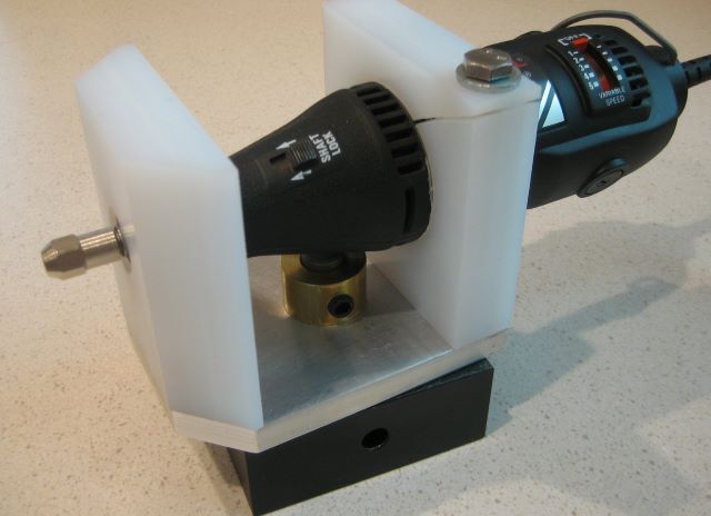
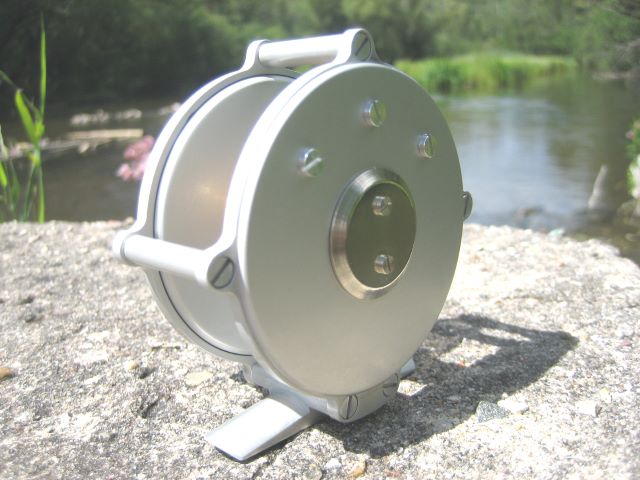
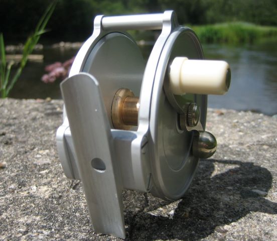
My reels to date have had ratchets of 642 bronze and pawls of natural Delrin. Delrin was the best of 9 plastics reported here on 7 May 2011. I chose bronze for the ratchet for its corrosion resistance and to assure that ratchet wear would not be a problem, as long as the pawl was plastic. Alloy 642 (Rtb 90) is perhaps an overkill and could be replaced by an alloy that is easier to machine such as 544 (Rb 80).

But classic reels have long used steel for ratchet and pawl, so I feel that I have to justify a departure from tradition. Steel has some obvious drawbacks: susceptibility to corrosion and more complex fabrication. This post covers my recent effort to make steel ratchet and pawl for comparative testing.

I chose 416 stainless. This is a martensitic (and therefore hardenable) alloy that is particularly easy to machine in its annealed condition.

For basic heat treat instruction, I read the book Heat Treatment, Selection, and Application of Tool Steels by William Bryson (not the travel writer).

When steels are heated above 1000F, they will oxidize and form “scale”. To prevent this Bryson recommends wrapping the steel parts, together with a small piece of kraft paper, in inconel foil. Once the package reaches 451F, the paper burns and consumes the available oxygen. But inconel is prohibitively expensive; it is what submarines are made from and they cost about $1 billion. I think that the reasonable substitute would be stainless bags from McMaster-Carr.

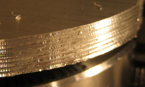
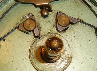
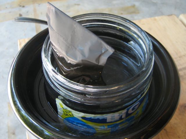
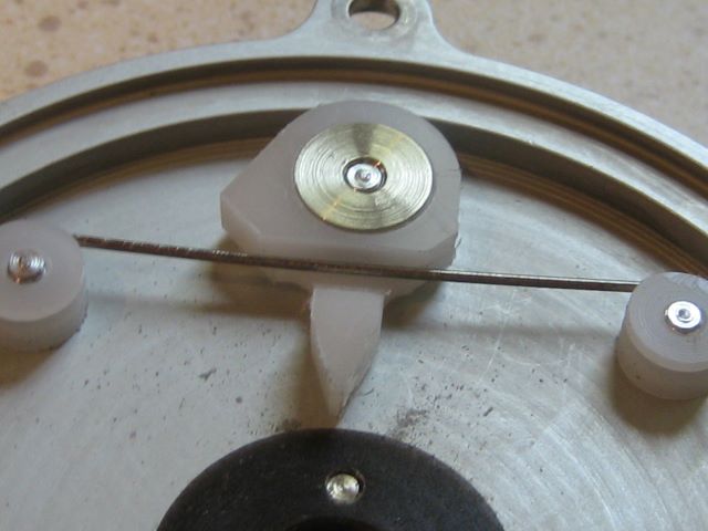
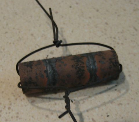
I chose instead to use an anti-scale coating. Bryson mentions PBC (Rose Mill Co.) but this is apparently based on borax, as it is limited to 1600F service. I used ATP-641 from Brownells, which dries as a ceramic casing. Of course I failed to read the instructions for application, so I did not realize that it should be thinned. It was difficult to get the parts covered with the thick solution, and I ended up with a very thick coating. As you can see, fine details of the ratchet and pawl are entirely obscured.

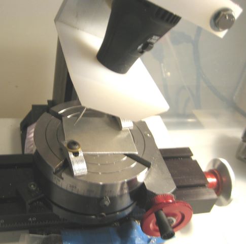
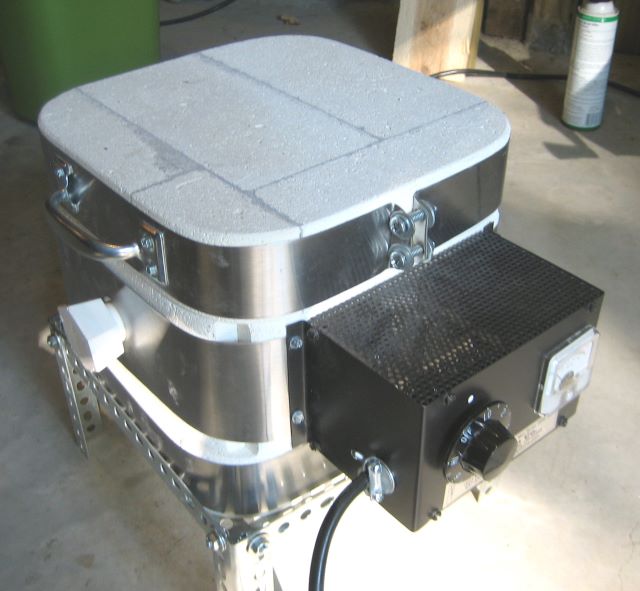
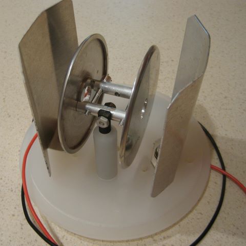
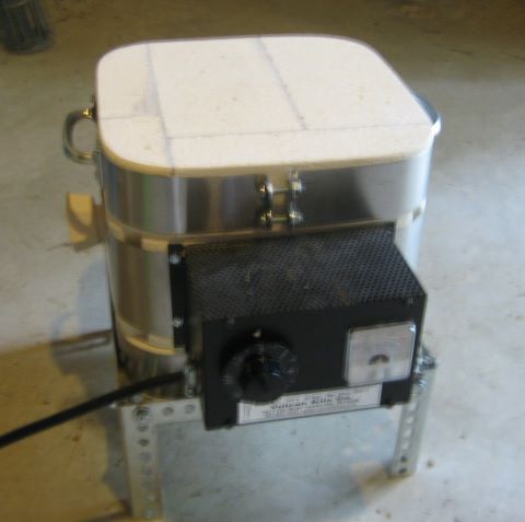
To heat the parts, I used the same kiln that I had when I tried silver brazing (23 June 2011). It is a Vulcan JK-1, and is equipped with a thermocouple. If you were trained in blacksmithing technique, you might get along with a charcoal forge and judge temperature by color. But I have a degree of color blindness that would make it impossible to know when I had “straw color”. The austenitizing temperature for 416 stainless if 1850F. For parts of 1/8 inch section, this should be held for 1/2 hour.

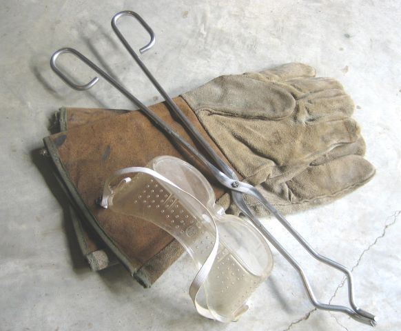
For safety, I was prepared with long tongs, welder’s gloves, and goggles.

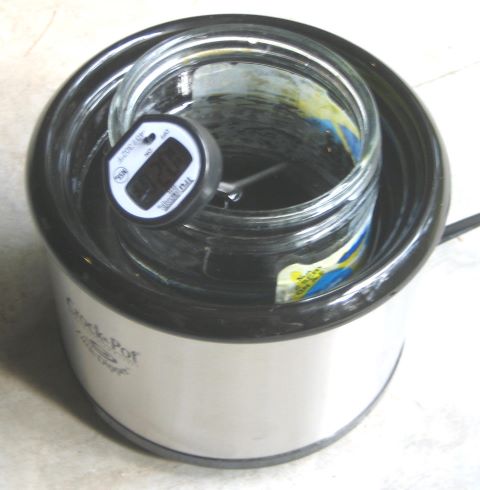
Once the parts become austenitic, they have to be quenched to form martensite. Now, 416 is particularly easy to quench; you have perhaps 30 seconds to get below 1300F. Air quenching would probably work, but I chose to oil quench instead. The reason is Bryson’s caution to not let the parts get below 150F before tempering. So I heated a jar of mineral oil in a small crock pot. This is a low wattage appliance, and it took about 45 minutes to heat the oil to 150F, Upon quenching the 1850F parts, the oil temperature rose to 173F. I had no more than 12 oz oil.

I tempered at 700F. I thought that this would provide the best combination of hardness (37 Rc) and toughness (22 Charpy). References: Atlas Steel and Carpenter. Tempering time for these small parts is 1 hour.
While the quenched parts are waiting in the oil bath, there is the problem of getting the kiln stabilized at tempering temperature. When you remove the cover, the air inside quickly cools and the thermocouple responds to this. But the walls are still hot and when you replace the cover, the air reheats. So you have to fiddle around for a while to get the temperature stable.
Now the disadvantage of oil quench becomes apparent. You can’t wipe off all the oil before putting the parts into the kiln. And if you reheat them to 700F and then remove the cover to control temperature, the sudden burst of oxygen causes them to burst into flame. Before doing this process again, I am going to carefully consider water or air quenching.

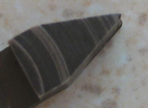
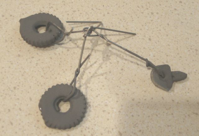
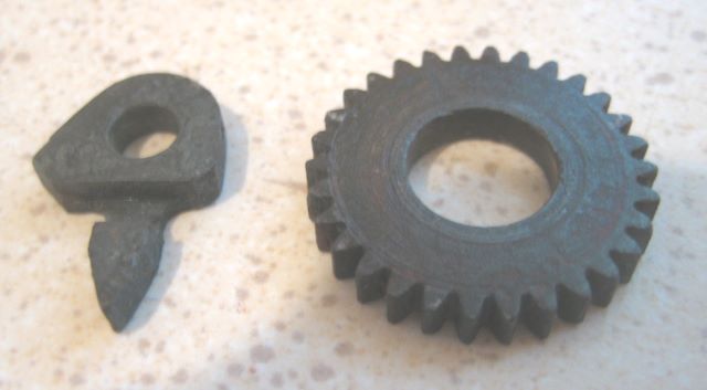
So here are the parts after tempering. Some of the coating has already flaked off.

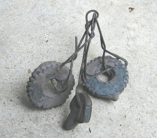
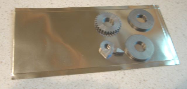
And here they are after I chipped off the rest of the coating. Not beautiful, and the dark surface doesn’t easily sand off. To get a bright surface again, you pretty much have to grind. I am not going to spend time making microgrinding wheels to work on 36DP gear teeth.

I am beginning to wonder if the anti-scale coating was worth the bother, since I am treating a stainless steel (although one that is not of the best corrosion resistance). While the parts were in the kiln, they sat on a rack that I made from stainless screen wire and 303 bar. This is the rack after a furnace braze operation at 1350F.

And here it is after austenitizing and tempering. Darker yet, but not much worse than the ratchet and pawl.

Note 10 Aug 2011: I posted a reference to this on Rod and Reel Maker’s Forum, and a question was raised about the tempering temperature. 700F is perhaps a little too high; could get “blue brittleness”. So I will re-do the heat treat, tempering at 600F. Also, will use stainless bags instead of the ATP-641. Hope to get better looking parts. The ratchet and pawl are going onto a fast gearmotor tester, and I don’t want them to be brittle. The bags: alloy 309 has better high temperature corrosion resistance than other 300 series stainless.

Posted in Heat Treating | Leave a comment

New Anodizing Cell

My first anodizing setup was reported in this blog (4 May, 2010). It used a small polypropylene jar with several fitted lids having different electrodes to secure the various parts. Since then, I have realized that anodizing an entire assembly is as effective and saves a lot of time.

So I have made a new anodizing cell with a larger jar (32 oz). Its diameter is the same as that of the first cell, 4 inches. This jar is purchased with a screw-on lid so the electrolyte (50% battery acid and 50% distilled water) can be stored in the jar.

Here is the setup for anodizing side plates and pillars as an assembly.

The cathodes are 0.040 aluminum (6061) and are 9 square inches each. The frame is supported from a titanium post by a fixturing pillar of aluminum. This temporary pillar becomes anodized in the process, but this coating can be easily stripped with lye when it is to be reused.
For anodizing at 6 amps/sq ft, this assembly needs 1.4 amps anodizing current. Time is 2 hours.

I could have included the reel foot in this assembly, but the jar was a little too small. So I do the foot by itself. It requires 0.22 amps.

The only other aluminum parts for this reel are two spool plates. To hold them I made a clamp of aluminum bars and screws. I clamp them on the OD of a hub because the IDs of the bores, in contact with bronze in the final assembly, need a complete coating. This temporary assembly needs 1.0 amps.

Because I am anodizing larger areas with larger currents, the electrolyte heats during the process. This is easy to detect because the voltage drop across the cell is dependent on temperature. To add thermal mass, I keep the cell in a bath of water. I try to keep the voltage drop in the 6 to 7 volt range by adding ice cubes as needed.

Update 18 Aug 2020: I now believe that titanium should not be used for the rack (the anode support). It is better to have an aluminum rack, although it will have to be stripped of the oxide layer each time it is used, which is done with a lye solution. Titanium causes a dark deposit on the cathode, and recently has spoiled several work pieces (anodes) for me. Best to have only aluminum in the acid solution.
Reading this post again, several years later, I realize that a “6 to 7 volt” range cannot be right. The acid solution must have been much hotter than I thought. Today with a good temperature control, the voltage drop is consistently in the 16 to 17 volt range.

Posted in Anodizing/Plating | Leave a comment

Finishing Plastic

To finish metals, I often use wet/dry sandpaper. The finest grit that I have on hand is 2000. That seems to me to be fine enough for metals; I don’t really want a mirror finish. But when I have tried to put a shine on Delrin, 2000 grit leaves the surface dull and unattractive.

Recently I ordered some pen turning blanks in order to have stabilized hardwood to make reel knobs. From Craft Supplies USA I also bought a pen blank of a plastic that they call “Alternative Ivory”. Before finishing the order, I noticed a “Micro Surface Pen Finishing Kit”. This is a set of 9 foam pads with abrasive faces, and the grits range from 1500 to 12000.

I made an Alternative Ivory knob and used the kit to finish it. By the time I got to 8000 grit, there was a pretty good shine.

So I then tried sanding a small piece of black Delrin, and that also worked well.

Posted in Abrading, Materials | 2 Comments

Engine Turning

“A gold hunting-watch, David, engine-turned, capped and jeweled in four holes,…” – Montague Tigg to pawnbroker in Martin Chuzzlewit by Dickens.

My current reel design has aluminum side plates and I have been considering how they might be decorated. Not that they really need decoration – many classic reels are quite plain – but a little bling might not hurt.

Years ago I saw a photo of an “engine turned” aluminum dashboard for a customized car. The decoration was made by chucking a wooden dowel in a drill press, loading the end with abrasive compound, then pressing down on the aluminum sheet while the motor is running. The circular scrapings were in a grid pattern and looked quite nice. I don’t remember how they positioned the material to get a uniform grid, but it seems as if a big X-Y table would be needed. The circles overlapped; it would take some practice to make each new circle obscure the scrapings of its neighbor.

Here is an informative article on this type of “engine turning”.

To adapt this technique to reels, one could still use the square grid. But it seems to me that a linear spiral would also be interesting, as shown below.

In recent private communication with Richard Westerfield, I became aware of the “rose engine”, which was one of the specialized engraving machines used by 19th century jewelers. This is a lathe with a pivoting headstock that that moves the chuck relative to a stationary cutting tool while the spindle turns.

There are some modern rose engines, and they seem to be of interest mainly to woodworkers. See Lindow-White.

There are also home built engines, see Rambling Rose and the MDF Rose Engine.

So how would I accomplish rose engine engraving for a reel sideplate? The old rose engines were stout machines that pushed a “graver” through the metal. Because I am unlikely to get/make such an engine, I would have to rely on some rotary engraving tool, maybe a Dremel tool. A rational approach would be to install stepper motors on my mill X-axis and rotary table, but I am not anxious to acquire CNC capability. Nineteeth century technology has its appeal; I am considering rose engine construction.

To engrave a 2.5 inch diameter sideplate, how big would the engine have to be? To answer this, I have coded (Visual C) a “virtual rose engine”. Here is what I can get with an engine that is only 3 inches from headstock pivot to spindle, with a rose cam of 4 inches maximum diameter.

This figure was made assuming a 4 lobe cam, with 12 indexings of the cam relative to the work. The cutting tool is on the horizontal centerline of the chuck to get a maximum figure amplitude from a cam whose radius varies by only 3/4 inch.

If the tool is located below the chuck center, the engraved band is more narrow.

Here the same 4 lobe cam is used but there are only 6 indexings of the cam relative to the work. The virtual rose engine is a tool to help me design a hardware engine and predict its capability.

Update 28 April 2017: Last year I built a CNC engraver for reel decoration. Here is an engraving example that is somewhat like engine turning.

This was not created by my “virtual rose engine”, but by arcs defined by my engraving software.

Posted in Engraving/Marking | Leave a comment

Silver Brazing

I like to use bronze for reel spool shafts. Portions of the shaft are the bearing journals, and it seems right to have bronze there, instead of aluminum. But bronze is heavy; the shaft of my first reel design was 1.15 oz, and that is a large part of the total reel weight of 5.4 oz.

A hollow shaft would save a lot of weight. Material at the center is contributing very little to shaft strength or stiffness. So I have made a shaft of 3 sections in order to be hollow at the center.

These 3 parts are to be joined by silver brazing. This shaft is for next reel`design, and it would be 1.20 oz if solid, but only 0.62 oz when hollowed.

For brazing, I bought 1 oz of STL-1205-655 from SRA Soldering Products. This melts at 1205 F. I put some chamfers on the 3 shaft parts to allow a little room for the solder.

Someone experienced with using a torch would probably have no problem brazing this. While I have done a lot of low temperature soldering (plumbing, electronics), I was not confident that I would know what to do with the torch. Fortunately, I had already bought a kiln so that I could harden steel. This is also a suitable heat source for brazing. SRA recommended 1350 F kiln temperature for brazing with STL-1205-655.  They also advised to preheat the kiln before inserting the part.

The paste is simple to use.  It is a mixture of flux and metals and comes in a  syringe.  Just apply it to the parts, assemble, and heat.


This is a model JK-1 from Vulcan Kiln Co. It has a manual heat control and a thermocouple with indicating meter.

Here is a grate that I made from stainless steel to support parts in the kiln.

This was the first time that I used the kiln, so I kept a record of time and temperature for the operation. The heat control knob is marked OFF-1-2-3-4-5-6-HI. I think that it is a bimetallic control of the type used on electric ranges; it duty cycled the heater as a range control would.

time      temp (F)     remark
3:04         70            set control to 2; kiln is closed and contains only the grate
3:14       500           set control to 4
3:24       900           set control to 5
3:34     1300           set control to 5.5
3:35     1350           set control to 5
3:37      1400          set control to 4.5
3:39      1400          put shaft onto grate (now glowing red)
3:40      1400          set control to 4
3:41       1425          set control to 3
3:43       1350
3:45       1350          shaft glowing red
3:46       1350          turn off, remove shaft, re-close kiln
3:49       1100          cooling w/ cover on
3:55         950
4:21         650
5:08        400

The cool-down rate is of interest because it shows that unpowered cool-down is too rapid for annealing many steels. To anneal, you would have to gradually reduce the control setting, and this might take hours. 416 stainless has to be cooled no faster than 50 F/hour until it is down to 1100 F.

Here is the shaft after brazing, covered with scale.

And here it is cleaned with sandpaper.

Finally, here is the machined shaft.

Update 6 Feb 2012: I have made 9 hollow shafts by brazing, but have had 2 failures. The failures show up during machining. Turning the several diameters imposes a rapidly reversing stress on the braze joint that exceeds anything that will be seen in service. The failure is due to insufficient braze metal in the pocket where the two pieces meet, and this pocket is hidden (up until the failure). I have now made a shaft and bonded the joint with Loctite 609. It machined with no problem. Refer to my post of 27 Aug 2010 for adhesive bonding. To make this bronze-bronze joint, I did not bother with activator.

Posted in Brazing | Leave a comment