
“A gold hunting-watch, David, engine-turned, capped and jeweled in four holes,…” – Montague Tigg to pawnbroker in Martin Chuzzlewit by Dickens.
My current reel design has aluminum side plates and I have been considering how they might be decorated. Not that they really need decoration – many classic reels are quite plain – but a little bling might not hurt.
Years ago I saw a photo of an “engine turned” aluminum dashboard for a customized car. The decoration was made by chucking a wooden dowel in a drill press, loading the end with abrasive compound, then pressing down on the aluminum sheet while the motor is running. The circular scrapings were in a grid pattern and looked quite nice. I don’t remember how they positioned the material to get a uniform grid, but it seems as if a big X-Y table would be needed. The circles overlapped; it would take some practice to make each new circle obscure the scrapings of its neighbor.
Here is an informative article on this type of “engine turning”.
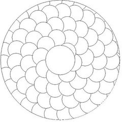
To adapt this technique to reels, one could still use the square grid. But it seems to me that a linear spiral would also be interesting, as shown below.
In recent private communication with Richard Westerfield, I became aware of the “rose engine”, which was one of the specialized engraving machines used by 19th century jewelers. This is a lathe with a pivoting headstock that that moves the chuck relative to a stationary cutting tool while the spindle turns.
There are some modern rose engines, and they seem to be of interest mainly to woodworkers. See Lindow-White.
There are also home built engines, see Rambling Rose and the MDF Rose Engine.
So how would I accomplish rose engine engraving for a reel sideplate? The old rose engines were stout machines that pushed a “graver” through the metal. Because I am unlikely to get/make such an engine, I would have to rely on some rotary engraving tool, maybe a Dremel tool. A rational approach would be to install stepper motors on my mill X-axis and rotary table, but I am not anxious to acquire CNC capability. Nineteeth century technology has its appeal; I am considering rose engine construction.
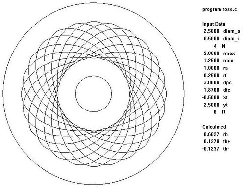
To engrave a 2.5 inch diameter sideplate, how big would the engine have to be? To answer this, I have coded (Visual C) a “virtual rose engine”. Here is what I can get with an engine that is only 3 inches from headstock pivot to spindle, with a rose cam of 4 inches maximum diameter.

This figure was made assuming a 4 lobe cam, with 12 indexings of the cam relative to the work. The cutting tool is on the horizontal centerline of the chuck to get a maximum figure amplitude from a cam whose radius varies by only 3/4 inch.
If the tool is located below the chuck center, the engraved band is more narrow.
Here the same 4 lobe cam is used but there are only 6 indexings of the cam relative to the work. The virtual rose engine is a tool to help me design a hardware engine and predict its capability.
Update 28 April 2017: Last year I built a CNC engraver for reel decoration. Here is an engraving example that is somewhat like engine turning.
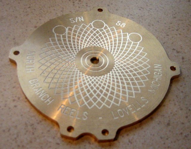
This was not created by my “virtual rose engine”, but by arcs defined by my engraving software.
