Parting, or lathe cut-off, is the operation of sticking a narrow blade straight into a rotating part, and (hopefully) making a continuously deeper groove until the part drops off of the chucked rod stock. A Google search on “lathe cut-off” reveals that many people have difficulty with this operation.
Making frame screws for my reels involves many parting operations. The operation was not going well, and this led me to discover the cause. The blade was not raising a chip, and I began to suspect that it was not properly sharpened.
A good explanation of blade sharpening is at CNC Cookbook. Here a diagram shows how to put top relief on a blade with the corner of the grindstone. I don’t believe that I could do this successfully while hand holding the blade.
But the cut-off blade holder that Sherline sells holds the blade at a 7 degree angle below horizontal. So this takes care of top relief without having to grind a scallop in the top of the blade. Unfortunately, this holder also removes all or nearly all of the relief of the end surface of the blade. As sold, these blades have an end angle of 10 degrees off perpendicular to the blade top. This is a good relief if the blade is held horizontal, which is usual. But in the Sherline holder, relief is effectively reduced to 3 degrees. Sherline instructs us to re-sharpen the blades with an end angle of 7 to 10 degrees, which means zero to 3 degrees of relief.
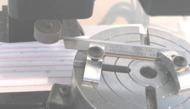
So I decided to test different relief angles. I clamped my blade to the rotary table on my mill and used a small grindstone (Dremel) to do the grinding. If I grind at 8.5 degrees (center of Sherline recommendation), I get a blade that will not penetrate even aluminum. At 10 degrees it is possible to part aluminum, but the operation is not smooth. At 12 degrees (i.e., 5 degree effective relief of the front surface), I get a nice, continuous chip.
For my first reel, I used stainless flat head machine screws to assemble the frame. This was expedient. For the group of 5 reels that I am now making, I want the appearance of “gun screws”, which have a simple cylindrical head. Also, it is not good practice to thread stainless into aluminum because the two are too far apart on the galvanic scale. I do anodize the aluminum parts, but this protective coating is unlikely to penetrate down into the tapped holes.
Gun screws are not widely available, and those that can be found are made of blued steel. Aluminum screws are also relatively rare. If I were making a reel of modern appearance, I would buy button head screws from Fastener Express. These are anodized by the supplier, and even come in a variety of colors. But there is no screw with the appearance that I want for my present reel design.
So I finally decided to make the screws, a repetitive task (5 reels time 10 screws/reel). The material that I chose is 7075-T6 aluminum. This material has 83 ksi tensile strength, 150 BHN hardness, and machines at 80% the ease of 2011 aluminum. I was able to buy 0.25 inch diameter stock from Speedy Metals.
Slotted screws often are damaged by over torquing and ill fitting screwdriver blades. I applied excessive torque to the first screw that I made, using a properly fitting screwdriver bit. It was damaged, but no worse than a stainless screw that I similarly treated.
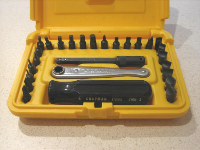
Here is a screwdriver set that I recommend, Chapman 8900. It has with 12 straight blades which are hollow ground.
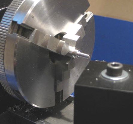
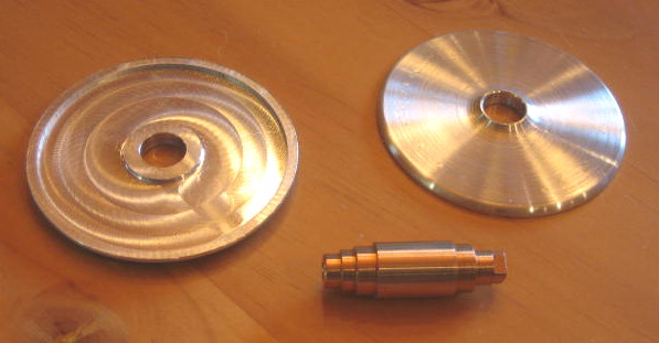
Making screws is straightforward. First profile the head and threaded portion.
Then cut threads with a die. This is a hand operation. For easy cutting, I made a crank handle that clamps over the lathe headstock shaft extension. You can see the white knob of this crank.
This post isn’t about machining fly reels, but North Branch Reels is the only blog that I have. This is about making furled leaders, a craft that takes less equipment and less skill than tying flies.
Furled leaders have no shape memory, so they don’t curl up like monofilament and create wind knots. Also, they don’t stretch when you pull a fly out of a tree branch, so there is less tangle.
I make furled leaders by the method given by Claude Freaner. This post provides supplementary information, photos and a diagram, that may be helpful.
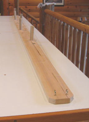
Here is the fixture, a 1×4 with five dowels and two cup hooks attached. Thread has been wound on; I use UNI-Thread 6/0 (a popular fly tying thread). I once tried using 2 pound monofilament but got kinks during twist. The UNI-Thread has proven itself absolutely durable; I have had no failures in 8 years. It comes in 200 yard spools, and this is enough to make 5 leaders.
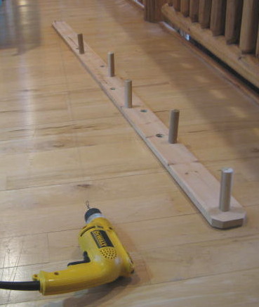
This is the pattern for winding thread onto the fixture. Particularly important is the interlocking of loops at four of the dowels. This is why the dowels are 1 inch diameter; it lets you easily drop the thread spool through. Note that runs 11, 17, 22, and 28 go past one post and on to the next.
Here one side of the butt has been gathered on a fishing snap and the leader has been unfolded. It is ready for the first twist. Near the middle of the unfolded leader I have attached a 4 oz. lead weight (also on a snap). It does nothing during the twist, but is a valuable third hand after the twist when the leader is re-folded.
This is a detail at the drill, showing a cup hook chucked in the drill, and the snap.
Here the first twist has been made and the leader re-folded so the second twist (reverse direction) can be done.
Both twists are now done, and the weight has been reattached. It is hanging at the end of the leader, which is untwisting somewhat as it relaxes.
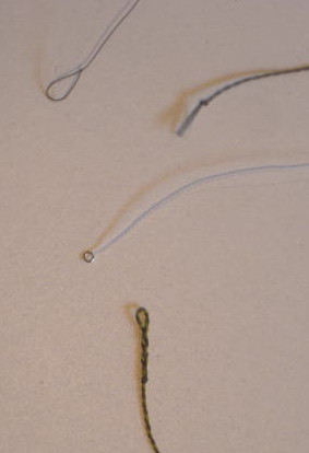
Here are the two ends of two different leaders. At the top is the tip and butt of my leader. I have made a Shorb Loop at the tip. The butt is secured with an overhand knot. I will cut this knot off after I have nail knotted the leader to the end of a fly line. The trick to making a neat nail knot is to NOT use a “nail knot tool”. Instead, use a loop of thread or monofilament to pull the tag end back under the coils. When I add tippet, I use loop-to-loop connection.
At the bottom of the picture are the two ends of a leader that I recently bought from Streamside Leaders. This is a more elaborate assembly. There are two colors of thread, which gives a snazzy appearance that may even provide camoflage. A loop has been formed at the butt, useful if you want a loop-to-loop connection of fly line to leader. I do not know how this was done. Several inches from the tip, there is a transition from thread to monofilament. I don’t know how this was done, either (or why). I detect no knots where monofilament begins and ends. Finally, a small metal ring is at the tip, and this may be helpful for loop-to-loop attachment of tippet.
Additional Note 8 June 2014 : I have a 2500 rpm electric drill and have been running 1 minute on the first, double length twist. Then 20 seconds on the second, folded twist.
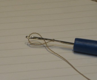
Procedure: Push Knit-Pick point between the two thread bundles about 1 inch above the leader tip. You have to untwist a 1/4 inch section of the leader in order to get the tool inserted. Push the leader up the tool shank past the latch, then grab the end loop and close the latch. Pull the end loop through. Push the end loop up the tool shank past the latch, then grab the newly formed loop and close the latch. (Photo illustrates this point.) Pull through and stretch out the final loop.
Refer to earlier posts titled “Results of Pawl Wear Test” (Aug 2010) and “The gearmotor that wasn’t a gearmotor” (Sept 2010).
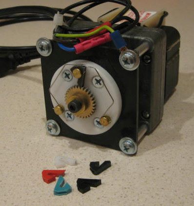
After discovering a possible misoperation of my first pawl test fixture, I built a new tester using a real gearmotor. This gearmotor has a shaded pole ac motor and a 3 stage geared reducer; one stage helical and two stages straight tooth.
This is a view of the new tester:
The new tester runs at 20 rpm (vs. 25 rpm for the first one), so I extended the test time to 7 days (vs. 6) to partly compensate.
The wear results are not dramatically different from those obtained in the first test, suggesting that the faux gearmotor did operate continuously while not being watched. Measured wear is, if anything, less in the second test. Perhaps the intermittant, ratcheting motion of the first tester was a factor.
The following table summarizes both tests.
Before trying plastic pawls, I tried pawls of aluminum, brass, and stainless (303). All of these produced rapid wear (of the ratchet, in the case of stainless). Any of the plastics is better than any of these metals. My bronze ratchet is alloy 642. It doesn’t appear to have worn as a result of testing plastic pawls.
I believe that low coefficient of friction is desireable in ratchet-pawl contact. Turcite X did less well than Delrin, but some other property must have come into play.
Update 8 Dec 2010: When I previously tested a 303 stainless pawl, it was with a 360 brass ratchet, and this caused wear of the brass ratchet in a short time. I just finished running a 303 pawl on the 642 bronze ratchet, 1 week, and there was no observable wear. I think that the difference is Rockwell B hardness of 80 for 360, vs. 90 for 642. For the present reel design, I will settle on a Delrin pawl, because the metal pawl is too loud.
Update 13 Oct 2011: It has just come to my attention that the material that I have called “Delrin” is actually acetal copolymer. There is a minor difference, read here.
The “Delrin AF” is this material from McMaster.
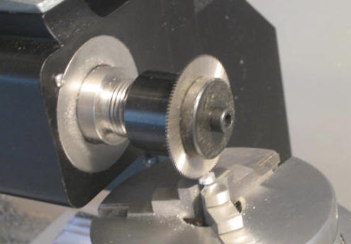
To fabricate nickel silver end rings, you have to neatly silver solder the flange to the web, then machine. But for aluminum end rings, you can find heavy wall tubing. I was able to get 3/8 wall tubing from Speedy Metals.
I bought the tubing as 1 inch cut-offs, with the idea that I could turn 3 or 4 rings from 1 piece, parting off between rings. The substantial length of tubing would provide the stiffness needed to avoid ring distortion from jaw clamping forces. This worked for the first reel, but I found parting off to be difficult with my Sherline lathe; it was very easy to stall the motor. So I decided to saw off short pieces in the future.
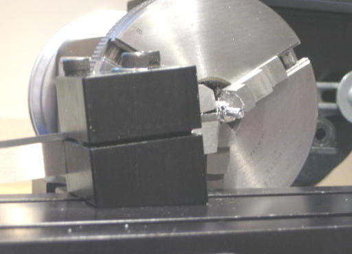
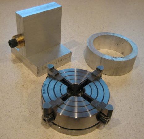
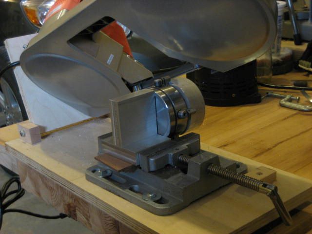
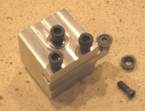
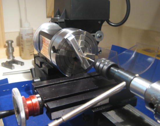
When sawing, the tubing must be firmly held. The 4 jaw chuck seem to be the best choice for this, so I made a fixture to hold the chuck under my power hacksaw. The brass part on this fixture has a 3/4-16 UNF thread that fits the back of the chuck.
In the future, I will buy tubing in longer lengths so it can be held in a cradle during sawing.
Here is a shot of the fixture in use
Turning the ring is straightforward. The ring does distort from jaw forces, but it helps to use a 4 jaw chuck instead of 3 jaw because the distortion is less. This distortion is not visible to the eye, but can be found with a dial caliper.
One of my rings was too narrow to clear the chuck jaws, so I made a sheet metal spacer to locate it farther out on the jaws.
Spool ends are a straightforward lathe-made part, if the design allows grip by a 3 jaw chuck. My design has a recess on the back side that lets the jaws grip in either the normal or reversed position. I use reverse position for the jaws so the grip is on a larger diameter. I make the recess by milling, before turning the front side profile. This recess requires a plunge cut, which is difficult to do with the lathe.
My design has a flat face, with a convex radius at the outer edge and a concave radius near the hub. The convex radius starts as a 45 degree chamfer which I then finish by lathe filing. I roughly form the inside radius by stopping the lathe bit (during facing passes) at pre-calculated radii. Then I finish this radius with a custom tool made from a 3/8 inch diameter carbide cutter (see previous post, on end plates). The cutter works quite well on Delrin, but less well on aluminum; I have to do a lot of manuvering to avoid cutting too wide a chip, since Sherline lathes have little reserve torque. I think that a satisfactory job could as well be done with the proper size round file.
I join the spool ends to the shaft with Loctite; see earlier post on spool assembly.
Antique Vom Hofe reels have end plates made of hard rubber. The modern version of this is Ebonite, used to make bowling balls. This material is available in a suitable form to those who want to be as authentic as possible; see Perfection Fly Reels.
My skills are not at the level where this degree of authenticity is warranted, so I make the end plates from black Delrin.
One advantage of Delrin is that it is a great bearing material. When I made my first reel, this point did not occur to me, so I went to the trouble of inserting Oilite bronze journal sleeves. For the group of 5 reels that I am now working on, I will just run the shaft right on the Delrin end plates.
Delrin is available in rod or plate form. I chose to use rod, but I am not yet convinced that it is the best choice. It may be easier to get the blanks that I need from plate. Here is how I proceed with 3.5 inch diameter rod, which can be purchased by the foot.
For the first reel, I cut slabs using my Delta 14 inch bandsaw. It worked, but I did not like doing it that way. The problem is that the saw has a conventional single phase AC motor, and the speed is fixed. This speed is suitable for most wood cutting, but is a little too fast for cutting plastic. Melted chips re-solidify in the saw’s slotted throat plate and make it difficult to feed the rod into the blade. It helped somewhat when I made a scrap wood sled to carry the rod because the rod was then up off the saw table.
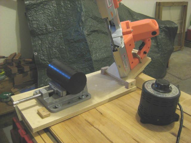
Later I bought a handheld bandsaw from Harbor Freight, because it had a universal (brush type) motor and could be speed controlled by reducing voltage. I made a pivoting frame so it would work more like a real metal cutting bandsaw. This saw has a speed control built into its trigger switch, but I found it somewhat difficult to control so I used a variac to reduce the speed. With lower speed, there is no problem with melted chips.
The fixturing shown here is not the final word; it is awkward to hand hold the rod down on the vise while cutting, and it will become more difficult as the rod gets shorter. So I plan to make a custom V-block vise, probably from wood.
After turning flat faces on the slabs, there is the problem of cutting the proper O.D.; jaws of the chuck are in the way. So I next put in the bores for the shaft journals. That allow me to clamp the slabs against a faceplate from the center. Here is the fixture, using a brass core with Morse Taper 1 to fit the Sherline headstock, and a Delrin plate to apply pressure.
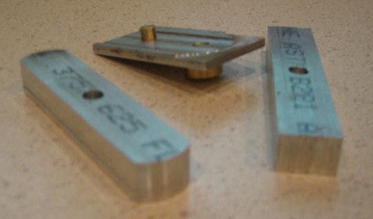
From here on, the material can be held on its finished O.D. with a 3 jaw chuck. But a spacer is needed to get the material parallel with the face on the chuck and to provide clearance from the chuck jaws. Here are two views of my spacer; the back side has slots to clear the vise jaws.
I fasten this spacer to the face of the chuck with Scotch double sided tape. This keeps it from rattling while turning, and falling off between chuckings.
The profiling of the plates can be done with any lathe tool, but I made a special one in order to get the finish as smooth as possible. The cutting element is a 3/8 diameter round carbide insert (RCMT-32.5), available from McMaster. It takes some hunting to find the special screw that secures this insert. (Google “CO-4011 insert screw”. It is M4 – 0.7 x 0.465)
Even with the well rounded cutting edge, visible machine marks are still left in the Delrin. I have decided to leave them as-is, they show that the reel was handmade from bar stock. If anyone has a procedure for polishing Delrin, I would be interested.
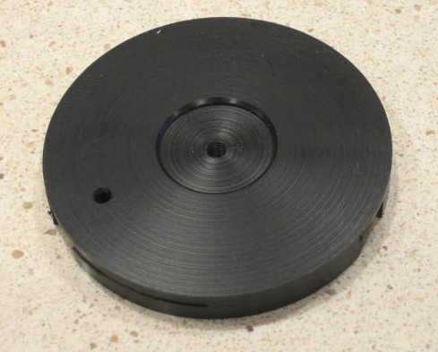
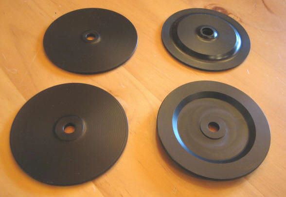
Here is a view of finished front and back end plates. The back end plate is dished to accomodate the click mechanism. The only operation not done is drilling for the pillar screws. I intend to make a drill template for this and use it on the end rings also.
The counterweight on my reel crank has hemispherical shape. Sherline sells an accessory that turns spherical shapes, and it is just what you would need to make more than a hemisphere. But I have found that I can get by with general purpose accessories.
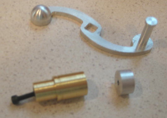
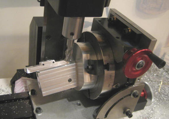
To make a hemispherical counterweight, I first made a brass mandrel that holds the work away from the chuck and encloses the screw that will secure the work. I make a blank for the counterweight that is cylindrical and has a tapped, blind hole.
I put the chuck, mandrel, and blank on the mill headstock, turned horizontal. I then fasten a lathe toolpost to the rotary table. The toolpost stays at constant radius, and I use X-axis feed between turning passes. Each cutting pass is made by turning the rotary axis through 90 degrees.
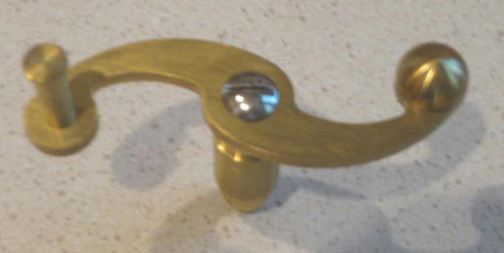
My first design for the reel crank (here in brass) was too “heavy” in the middle.
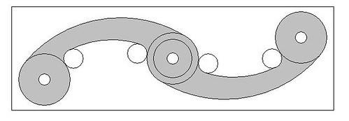
So back to the drawing board. Here I have reduced the diameter of the center circle, and moved one small inside radius to make the arm thinner. All curves are arcs of a circle.
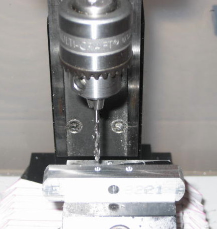
Fabrication starts with drilling location holes for the handle, counterweight, and shaft.
Then I plunge mill four small holes which become inside radii.
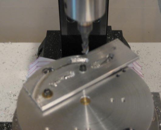
All the larger arcs are milled on the rotary table. The tool plate was carefully planned to hold the material in the correct positions.
This photo illustrates the emergence of the crank from bar stock.
There is a standard for the shape of a reel foot, and I observe it to a reasonable degree.
To hold the stock for initial sizing and drilling, I have made vise jaws with rabbets.
The standard calls for an 0.156 radius at all four corners, but it is time consuming to get a good tangent at each end of each arc. So I put a single large arc on each of the two ends. Many commercial reels also do this.
To quickly position the stock, I have made a small fixture that pilots onto the center of the rotary table and onto a tooling hole in the center of the part. The stock fits down into a groove that ensures centering over the rotary table.
Now back the the vise to drill holes for mounting screws.
My Sherline mill has just a short vertical travel, so I find it easier to move to the lathe for tapping. A 4 jaw chuck holds the stock.
The bottom of the foot is an 0.35 inch concave radius. Sherline holds end mills up to 3/8 inch shank diameter. So I make multiple passes with a 3/8 ball end mill to form this radius. Later, I sand it using a dowel as a sanding block.
Next I cut shoulders at each end to define the pedestal in the middle. These are radiused with a 1/16 inch corner rounding bit. Getting a smooth tangent at each end of the arc is a problem.
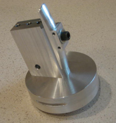
Next I cut the convex radius on the top. The standard is not definite on this surface, is it cylindrical or conical? If conical, it could be cut on a lathe by bolting the stock to a mandrel. But I decided to make it cylindrical, so I do it with the rotary table, using a fixture that sets the required 7.5 degree angle.
Here is a better view of the fixture.
Finally, a group of feet in process. These will be sanded and then anodized.