Engraving Practice

The engraver is running; here is a practice part.

This was done on scrap bronze with a .018 inch diameter end mill turning at 24000 rpm and travelling at 4 inches/minute. The groove is about .005 inch deep.
My design software is Vectric Cut2D, which I highly recommend. Its use is very intuitive.
Time to start a new reel.

Posted in CNC, Engraving/Marking | 8 Comments

First CNC Part

My CNC engraver has progressed to the point that it is ready to use. Before buying design software, I decided to try hand coding a G code program.

The task here will be to mill the complex perimeter profile of the rear end plate (or front end ring) of a raised pillar reel. The blank will be screwed to an aluminum tooling block that is clamped to the X-Y stage.

To align the block, I have made a brass pin that goes through the block and screws into a tapped hole in the stage. A test indicator mounted to the milling spindle show total runout.

I did not buy stepper motors with double shaft extension, which would allow manual cranks for axis zero adjustment. But I find it reasonably easy to turn the screws by gripping the acme shaft collars on the thrust assembly.

Once the spindle is centered, I can move (under CNC control) to one of the mounting holes and hold a tapered pin in the spindle to get angular alighnment.

Here a blank is screwed to the tooling block. This small blank is the waste material from making a front end ring.

To create a G code program for the outer profile, I set up an Excel spreadsheet that calculates the end points of the 20 arcs that define the profile. The top section of the spreadsheet does the calculations, and the lower part organizes the X and Y coordinates into a table that can be read as G code.

And here is the profile milled into the blank. It is not perfect; there is a visible cusp at each point where the base circle meets a fillet at each side of a lag. I was able to trace this problem to an error in the Excel spreadsheet.

To turn the spreadsheet into a G code program, I export it as a “formatted text (space delimited)”, which has extension .prn . After editing out the calculations in the top part of the file and changing the extension to .txt, the file is ready for use by a G code interpreter.

Note 3 Jan 2020: The main intended use of the CNC machine was engraving. This post shows that the intricate outline of a raised pillar end plate could also be profiled, perhaps saving much time of manual mill operation. However, I have continued to do the profile manually. As you will see in an upcoming post, I had a lot of trouble with cutters working loose from the spindle chuck. This traumatic experience discouraged further work with “heavy” milling cuts.

Posted in CNC | 5 Comments

CNC Control Panel

The control panel for the engraver is now wired.

The front has some switches to give me direct control of stepper enable, spindle power, etc.

Here is the back side. There are three switching power supplies.

If there are any EMC problems, I may have to put all this inside a metal enclosure. At the start, I am relying on cable shielding and optical isolation.

Here the engraver, control panel, and PC console are connected.

I can jog the axes around, but now have to learn enough about G code to start cutting metal.

Posted in CNC, Engraving/Marking | 2 Comments

Wired

I now have all the wiring anchored to my CNC mill.

Quite a bit of the labor was in mounting the limit switches.

The engraving mill will connect to its control panel by 7 four pin connectors: 3 for step motors, 3 for sets of limit switches, and one for the spindle motor.

Posted in CNC, Engraving/Marking | Leave a comment

The Motion Controller

I have purchased the motion controller and stepper driver for my engraver.

The two boards are KFLOP and KSTEP from dynomotion.com. They communicate together by a 26 line ribbon cable, and controller KFLOP talks to a PC console by USB.

What I find remarkable about the stepper driver is that the power devices have no conventional heat sinks. Each SO-8 package here contain two FETS. There are 8 H-bridges to run 4 steppers.

KSTEP can be jumper programmed to run a motor as large as 5 amps. My steppers are NEMA 17 size and rated 1.5 amps.

Dynomotion, free of charge, provides all the software needed for CNC operations.

Program “Kmotion” is used for system setup and provides the integrated environment for C programming. Program “KmotionCNC” is the controller that runs G code. Programming in C is not really needed; the setup established with Kmotion screens is saved (as a machine written C program) to initialize the controller at each power-up.
The Dynomotion proprietor is a California resident and is quite pro-active in answering all questions by Email, Yahoo Group, or CNC Zone forum. No Chinglish interpretation needed.

Posted in CNC, Engraving/Marking | Leave a comment

Engraver Frame

I have now built the gantry frame that supports the z-axis actuator and the engraving spindle.

The gantry attaches to the 12×12 inch baseplate of the X-Y table, shown in my previous blog post.


The spindle is a WW-650 from Wolfgang Engineering. It uses watchmaker collets and the brush type dc motor of a “rock crawler”. With the 2:1 speed increase by the belt, the spindle will run at 24000 rpm.

Next comes electrical work: route, shield, and anchor motor leads; install limit switches and their actuators; build electrical panel.

Posted in Engraving/Marking | 6 Comments

X-Y Table

This is the next step toward a CNC engraver, a complete X-Y table.

The structure here is three sheets of 1/2 inch thick MIC-6: 6×6, 6×12, and 12×12 inches. They provide a 6×6 work surface with motion of nearly 6 inches in each of two directions. Significantly, the heaviest pieces have the least motion.
The next step will be construction of a gantry to support the z-axis.

Posted in CNC, Engraving/Marking | 5 Comments

Y Axis Life Test

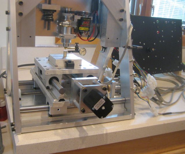
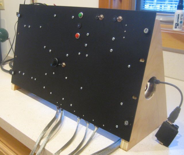
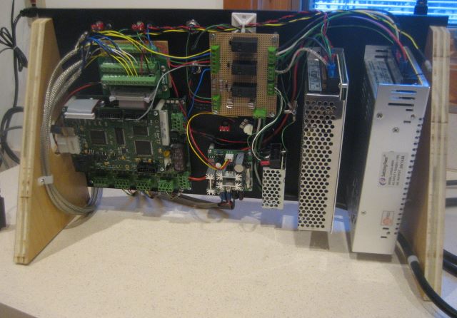
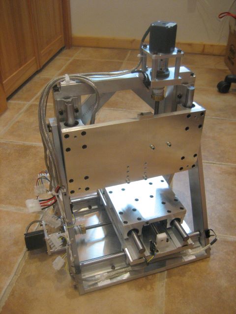
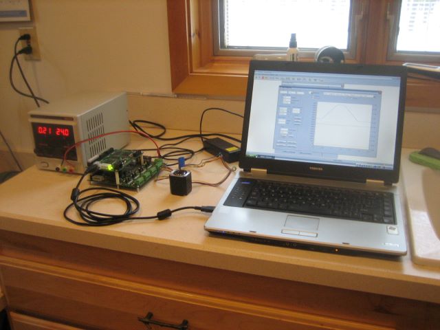
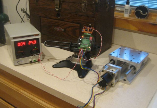
For the engraver Y axis, I have made a temporary limit switch bracket of wood, and wired a relay to change the travel direction at each limit.

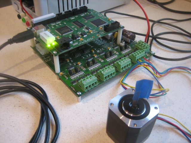
As initially assembled, the NEMA 17 stepper would move the table smoothly at 1.0 amp current limit. But during the first 4 hours of operation, the motor increasingly labored. I raised the current limit to 1.2 and then to 1.4 amps, but it was obvious that this was not successful operation.

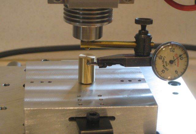
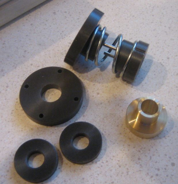
The problem was that as I made the nut and thrust parts (for the first time), I had not thought out the sequence of machining operations well enough. So part surfaces were not parallel enough, or perpendicular enough, for smooth running. I made the necessary corrections and in the process changed two of the thrust parts from natural acetal to teflon filled acetal (i.e., Delrin AF).

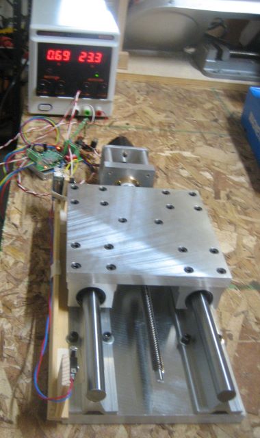
The slide now ran smoothly at 0.8 amp current, but not at 0.5 amp. At 0.8 amps, I then ran 100 hours continuously, travelling the acme nuts more than 5000 feet. During this run, the space between the two nuts increased by no more than .002 inch. So I am quite satisfied with the wear rate.

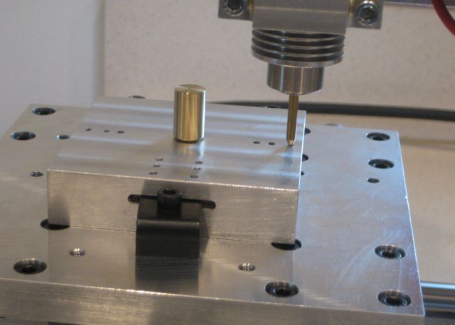
Rotation of the thrust assembly requires more torque than for the anti-backlash nut assembly, and I thought that the Delrin AF thrust parts represented an improvement over natural acetal. So I have now re-made the plastic parts of both assemblies in Delrin AF.

My intention is to briefly run these parts and then decide between natural and teflon filled acetal.

A note on acetal components: when I first tapped the two acme nuts, they each felt like they closely fit the acme screw. This is in contrast to a brass nut, for which the clearance in the standard acme thread can be felt. I believe that the apparent absence of clearance is due to plastic “flash” at all the sharp corners of the thread. During the first few hours of nut operation, this material is turned into loose debris and the nut then has normal clearance. So a spring loaded assembly is needed to obtain zero backlash, despite the initial feel of the plastic nuts.

Update 9 Dec 2015: I ended up doing a 100 hour test on the Delrin AF nut also. Again, the total wear of the two nuts did not exceed .002 inch. I have no reason to think that there is a difference between natural acetal and Delrin AF, for this application.

Posted in CNC, Engraving/Marking | Leave a comment

Alan’s Reels

Home shop machinist Alan has made these two reels from my plan set for “Fixed Spindle Reel”.

The end plates of the spool are darker than on my reels; I think he may have dyed them instead of electrolytic coloring.

Posted in Reels by Readers | Leave a comment

Y Axis

Now I have mounted the linear actuator on the slide, and have a working Y axis for my CNC engraver.

Driving the motor here is a board based on the Toshiba TB6560 IC. Like any stepper driver, it requires logic signals for enable and direction, and a pulse train to set the rate of stepping. To test the driver/motor combination, I made an oscillator circuit from a 555 timer. This oscillator runs at 400 Hz, so the slide travels at

400 steps/sec * rev/(200 steps) * 0.0833 inch/rev = 0.166 inch/sec

The stepper motor is rated 42 in-oz driving (76 in-oz holding) at 1.5 amp current. I found that 1.0 amp current is enough to smoothly move the slide. At 0.8 amp there are audible failed steps. Obviously there is binding due to imperfect alignment of the drive train, and this causes motor loads in excess of the ideal case. I have played around with the alignment, and do not expect to make much improvement. Fortunately, the loads that I am seeing are within the capability of the NEMA 17 stepper. My plan is to run the steppers open loop, but I can easily see the advantage of closed loop.

The next step is to set up a life test for the acme nut and the thrust bearing. If this is satisfactory, I will get material to make the rest of the machine.

Posted in CNC, Engraving/Marking | Leave a comment