
I have now built the gantry frame that supports the z-axis actuator and the engraving spindle.
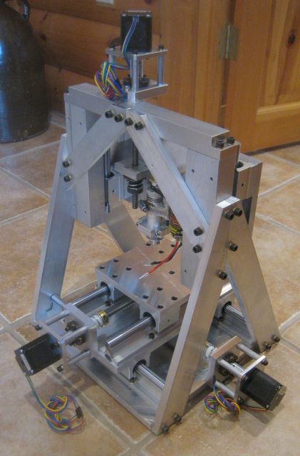
The gantry attaches to the 12×12 inch baseplate of the X-Y table, shown in my previous blog post.
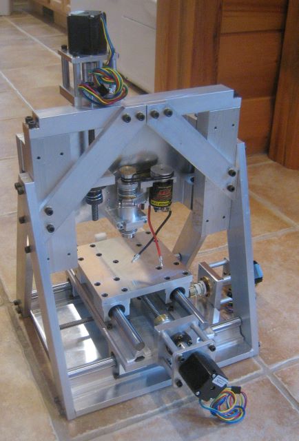

The spindle is a WW-650 from Wolfgang Engineering. It uses watchmaker collets and the brush type dc motor of a “rock crawler”. With the 2:1 speed increase by the belt, the spindle will run at 24000 rpm.

Next comes electrical work: route, shield, and anchor motor leads; install limit switches and their actuators; build electrical panel.

Wow pretty original design! Looks really solid, way more solid than typical routers.. I guess you can add some protections against chips and dirt, at least on y axis. Great work!
Ignacio,
Before I spend a lot of time on shields for the screws and rails, I am going to try a retaining wall around the 6×6 work platform
Dave
would be great if you had drawings and a parts list to go along with this build real nice work as usual this is my #1 site to go for information on reel building
Not sure if you’re using the current motor for testing because it was on hand or if you plan to use it on the final engraver, but I know that brushless motors off some advantages over the brushed variety. The speed controller will usually have built in braking to stop the motor quickly, rapid adjustment to the speed changes, completely sealed, and loads of torque just to name a few. It’s possible that none of those are a requirement at this time, though.
My personal experience is with the motor in the Mini e-Revo. Mine has taken quite a bit of abuse from all sorts of wet and muddy situations without fail. Clearly, this is not the same conditions as it would see in an engraver, but an example of it holding up to harsh treatment.
https://traxxas.com/products/parts/motors/velineon380motor
I’m also surprised to see that there was negligible difference in wear between the natural acetal and the Delrin AF. Maybe it would take longer test periods to determine a difference or possibly one may hold up better with dust particles than the other.
Keenan,
The motor was supplied with the spindle by Wolfgang Engineering. There was also a bracket for mounting the two but I discarded it and made my own mounting. That is why you see a hose clamp in the photo.
I am aware of brushless motors being available for the rock crawler application, and will upgrade to that if brush life of the present motor is not satisfactory. As an interim measure, I bought two spare brush type motors. They are very cheap compared to the brushless.
Dave
Completely makes sense and in the area of what I figured. It’s not like there isn’t any trade-offs going from one to the other. By the way, this design looks extremely solid and should prove to yield some very nice results. Especially if you can manage a 4th axis to allow curved surfaces.
I will be taking notes on the progress, for certain!