Threading with the Minilathe

I have had reason to single-point some threads recently. This was motivation to further improve my Minilathe so that threading is easier.

First, the spindle that carries the intermmediate cluster gear needs a brass shim (oblong) to bring the two meshes into axial alignment. The shim here is .062 inch thick. If this is not done, some gear arrangements are bound up with gear faces rubbing. The same axial alignment would be achieved with a simple round washer shim under the mounting plate for this spindle, but this would also reduce the space available for puller jaws.

I also replaced the thin washer at the nut with a thicker one.

I am not so bold as to try threading under power; there is not enough control. Fortunately, Little Machine Shop sells this spindle crank, part 3897.

Pull the line cord plug while you have this installed.

The plastic first gear and last gear (A and D) require a puller to remove. I bought this one at the auction site, but it was entirely unworkable.

Here I have modified the puller to make it easy to use.

1. Discard the two cross bolts.
2. Grind the jaws at the end of the arms so they are thin enough to get behind the gears.
3. Install two pins in the cross bar so the arms do not fall off.
4. Cut off the flimsy tommy bar and replace it with a knob.

Finally, I made my own chart of change gears.


Note that there are two setups for 1 mm pitch, one if you have bought the 21 tooth gear from Little Machine Shop and a somewhat less accurate setup if you do not have it. None of the the metric pitches are exact, but close enough for most purposes. The last column of the chart shows the ratio to true pitch.

Posted in Uncategorized | Leave a comment

Terry’s First Reel

Terry is an active bamboo rodmaker, now from Idaho but with background in Michigan. I met him once at the RKP rod shop. He has equipped himself with Grizzly mill and lathe and is starting out on reels. This is his first.


The pawl and ratchet are Delrin, an application that I strongly advocate.

Posted in Reels by Readers | Leave a comment

Internal Grooving

When I first got a lathe, I bought a group of randomly selected turning tools from the auction site. These two were a mystery to me and I never tried to use them.

This morning I was browsing through Youtube videos and I came across this one: Making Grooving Boring Bars
Duh. They cut an internal groove, as you might want for an o-ring. Might be useful on a reel where the o-ring is a substitute for a “tolerance ring”, allowing a low precision press fit.
The small one makes a 3/32 wide groove and the bigger one makes 1/8.

Posted in Cutting, Turning | Leave a comment

Lathe Bit Grinding, Redone

I posted the article “Lathe Bit Grinding” on 1 July 2013. Since then I have arrived at a better scheme, as described here. Bit grinding is somewhat an art and you will find many alternative styles of lathe bit. My goal has been to find a method that is quick and repeatable, producing a bit that is easily re-sharpened. All grinds are made with the tool held firmly against a spacer plate on top of the tool rest.

Here is a borrowed illustration which establishes nomenclature for lathe bits ground from high speed steel:

Image taken from the web site Instructables.com

My first metal lathe was a Sherline. You can buy pre-ground bits from Sherline, one is shown here. Initially I tried to reproduce this grind myself.

These bits have zero Back Rake (see nomenclature illustration) and the entire cutting edge (intersection of side and top surfaces) is very near the height of the bit blank. When the bit is sharpened by additional grinding of the side, the height of the cutting edge is reduced (as the edge moves down the Side Rake) and shimming of the bit (for use in a simple tool post) will be needed. But what is difficult about sharpening this bit is that the ground surface on the side is flat, whereas a grinding wheel has a radius. It would be difficult the hand hold the bit and make new side surface that is flat. Sherline undoubtedly has good tooling for producing this grind.

The grind pattern that I am using includes some Back Rake, and reduces the cutting edge height by .020 inch or so right from the start. So I am always shimming underneath my lathe bits.

It is easy to measure the edge height with a micrometer and determine the amount of shim required. My frequently used Sherline tool post needs the edge to be at 0.250 inch (i.e., the full height of the blank). The larger tool post for my Minilathe requires 0.332 inch. I think that it was designed for 8 mm tool blanks (0.315 inch) so at least 0.017 inch shim is always needed.

I made a selection of shims from brass shim stock and scrap material.

You could make a very complete set of shims from a feeler gauge kit.

These are Sherline tool posts for 1/4 inch bits, for 3/8 inch bits, and a “rocker” tool post.

The rocker is supposed to eliminate the need for shims but I find it to be fussy to set tool height and so seldom use it. Much quicker to measure the edge height and then select a few shims.

This is the Minilathe standard tool post. I use 1/4 inch bits in it, which need at least 0.082 inch shim. The greatest part of this shim pack is in a brass part with a step that provides an alignment edge. The step width is set to locate the bit under the clamp screws.

My grinder is a Delta that you would find in many hardware/home supply stores. The tool rest angle can be set in increments by the radial serrations you see on the mounting lug. The increments are too coarse for the purpose of bit grinding.

One of the increments sets the surface of the rest in line with the center of the 6 inch diameter wheel.

Here is a sketch of the grinding geometry. I have made a 1/8 inch thick plate to set on top of the tool rest. If I hold the bit flat against this plate, the relief angle of the grind is asin(0.125 / 3.0) = 2.4 degrees at the bottom of the bit. (3.0 is the wheel radius.) But at the top of the bit, 1/4 inch higher, the relief angle is asin(0.375 / 3.0) = 7.2 degrees. This is the effective relief angle at the cutting edge.

So here is a view of my cover plate for the tool rest.

It has some lines engraved as guides for grinding.

Following are the steps in grinding. I show a tool bit that is already ground, rather than a new blank.

The first grind is on the end. I hold the bit flat against the cover plate. The End Cutting Edge Angle is 25 degrees. The End Relief Angle is 7.2 degrees at the top of the bit.

The second grind is on the side of the bit; again I hold the bit flat against the cover plate. The Side Cutting Edge Angle is 10 degrees and the Side Relief Angle is 7.2 degrees at the top of the bit.

When re-sharping a bit, this is often the only grind that needs a re-touch.

Finally, grind the top of the bit, again holding the bit flat on the cover plate. The Back Rake Angle is 10 degrees and the Side Rake Angle is about 7.2 degrees at the cutting edge.

This grind can be eliminated for a tool meant to cut only brass.

End Relief, Side Relief, and Side Rake are all curved surfaces (3 inch radius). This makes no difference in how the tool preforms.

My grind pattern has a 75 degree included angle at the tip, and that seems to be good for getting into a square step. But the tool post has to be turned at a small angle, as shown here.

Quick Change Tool Posts have height adjusters that eliminate the need for shims under the bit. But, if I understand them correctly, they have to be mounted square to the cross slide and so some special bit shape would be needed for corners, perhaps a negative Side Cutting Angle. The freedom to rotate the tool post seems to me to be so important that I have never invested in a QCTP.

Update 20 Aug 2020: I just found this article, Hoffman Article. It says that I am wrong on tool height above the grinding rest, that instead of aiming for 7 degrees at the top of the bit you should have 7 degrees at the mid point. This is because a properly stoned tool will have a little material removed at the top and bottom of each face, and the true relief angle will be midway between the top and bottom angles that the grinder produces. He has some good photos that show this. So maybe my tool rest cover plate should be 1/8 inch thicker.

Posted in Cutting, Turning | 2 Comments

Alaska 2019

Last summer, we had a good partial day of fishing on a creek near Juneau. We decided to make a longer trip this year, and so went to a fly-in lodge northwest of Anchorage. The trip was by float plane.

There is no way to get there by road, but you might make it by dogsled in the winter.

The lodge is on Lake Creek, a tributary of the Yentna River. Lake Creek is not fed by glacier melt, and so runs clear.

The lodge building:

Guest cabin:

Rainbows would take sculpins, mice, and several types of streamer.

There were also grayling.

King salmon were present. This one may have had an encounter with a seal before going upstream.

One day, we went up nearby Fish Creek to a lake full of northern pike.

The highlight of that day was getting close to a moose.

Posted in Fishing | 1 Comment

Power Hacksaw

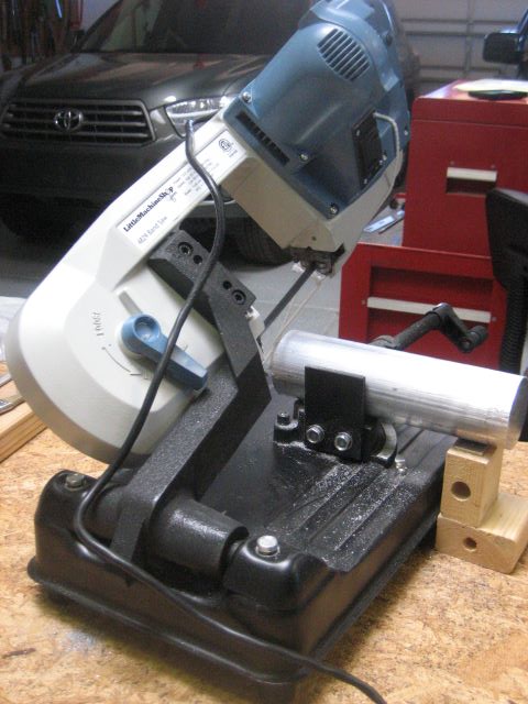
Before milling or turning, stock typically needs to be cut to length. My first tool for this task was a handheld power bandsaw lashed to a plywood frame.

This worked quite well, and is still functional. The reason that I have tried other means for cutoff is that it did not do well with large (say 3 inch diameter) round stock; the blade did not travel straight in the vertical plane. Part of the reason for this is that it is still a handheld tool and it is difficult to maintain constant pressure during a lengthy cut. Also, the wood frame is too compliant.

Next I purchased a bandsaw from Little Machine Shop.

This was better because the frame was stiffer. But after a year of occasional use, the rear guide assembly failed. Again, this is still a handheld tool and I was probably forcing it too much. LMS sent me a new guide assembly and it is again working.

Large, free-standing metal bandsaws have hands-free operation and should perform better than either of these tools. They also have limit switches to shut down the blade at the end of the cut. But I do not have room in my shop for this.

If you search for “power hacksaw” on Youtube, you can find videos of many homemade saws. Invariably, they involve a crank to achieve reciprocating motion. This kind of gadget has quirky appeal; I decided to try my hand.
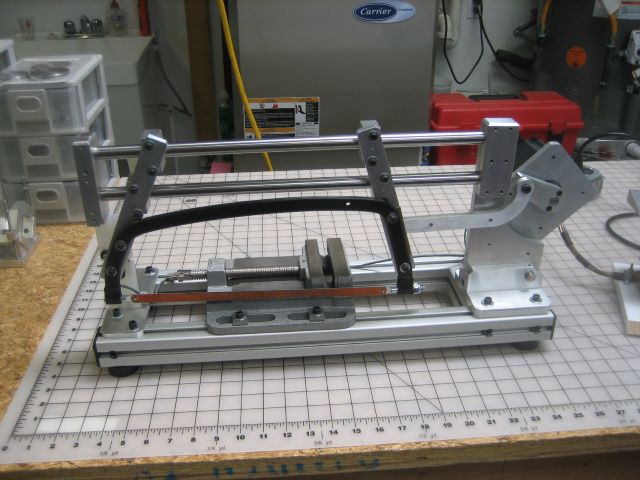
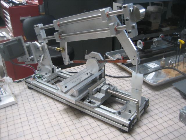
Here is the result.

What is different in my design is the use of a large (NEMA 34) stepper motor. This avoids the cost of a gearmotor and the complexity of two stages of belt drive.

Two more photos:

The limit switch:

The motor control: a 48 volt supply, a step motor driver, and an Arduino Nano to generate pulses at a ramping rate.

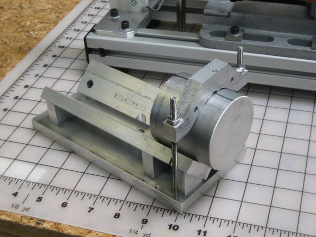
This is an auxiliary fixture to hold large round stock.

Here is an extra weight for the front end.

Design and Construction Notes:
1. The frame for the saw blade is from a Stanley hand saw (STHT20138). The additional bow under blade tension is appreciable and must be considered when drilling holes in the mounting brackets, i.e., have the blade under tension when you spot the hole locations.
2. The fit of the blade end holders in the frame is loose. I was able to improve the squareness of the saw cut by inserting shim stock into the gaps.
3. The base is made from 1.5 x 1.5 inch “T-slot” material. Guide rails are 5/8 diameter steel shaft.
4. I tried Oilite for the linear bushings, but could not align well enough to prevent binding. Final bushings are teflon filled acetal.
5. The motor is rated 640 in-oz (at 5.5 amps/phase) but I think this means holding torque. The relevant rating is 475 in-oz driving at 100 rpm and 48 volts. 48 volts is much more than needed to push 5.5 amps through the 0.43 ohm winding resistance, but is needed to obtain a sufficient rate-of-change of current (4 mH/phase).
6. The motor has 200 full steps/rev but its driver is set to “microstep = 2”, so 400 pulses are needed per revolution. I run at 1.0 rev/sec, so the pulse source is a maximum of 400/sec. On acceleration, I ramp from 40 to 400 pulse/sec. I think that a 400/sec constant source would be OK (maybe a 555 timer), since there is no problem recovering from a stall when the source remains steady at 400/sec.
7. In operation, 0.7 amp is drawn from the 48 volt source, or about 34 watts. Most of this is accounted for as ohmic loss: 2 phases * 0.43 ohm/phase * (5.6 amp)^2 = 27 watts. The supply for the Arduino is just a 5:1 resistive divider from 48 volts. Wiring for the limit switch should be shielded.
8. The crank length is 2.0 inch, so the push available to the blade is 475 in-oz / (16 oz/lbf * 2 in) = 14.8 lbf. The crank grips the motor shaft with a steel shaft collar. Link pivots are shoulder screws running in bronze bushings, oil lube.
9. The two guide shafts together weigh 3.5 lbm and are nearly centered over the cutting point. Including the saw frame, the total down force at the cut is about 5 lbf. The machine runs without stall at this cut pressure. But if I add the auxiliary 1.8 lbm weight at the front end (increasing the down force at the cut to about 8.5 lbf), stall is a problem. I am using a 14 tooth/inch blade, but did not see much difference with 24/inch. NEMA 34 step motors of twice this rating are available and should allow use of the extra weight. I assume that this would increase the cut rate.
10. Cutting is slow but square. I can do other tasks while the saw runs.

Here is a parts list. I have not been careful about fastener quantities, and I did not even try on small items like standard flat washers, wires, switches, etc.

Update 15 Oct 2019: I have removed several previous updates concerning stall problems with the hacksaw. Problem turned out to be misalignment of the linear bearings causing jam. Every time I loosen/retighten the blade, I have to realign. Four bearing blocks are held by 2 screws each; loosen and retighten these to realign.

Here is the vertical saw that I made from my first bandsaw. Will keep 24t/inch blade on it for fine work.

Update 7 Nov 2019: To get satisfactory operation, I had to make two modifications to my original design. Mod 1 was to relocate the center of crank rotation. This I did by drilling new mounting holes in the motor plate. Now the original dogleg crank is replaced with a straight crank.

With the original crank location, the tangent of the crank angle (relative to the direction of blade frame motion) was too large and reciprocating motion would lock up even without a cutting load.

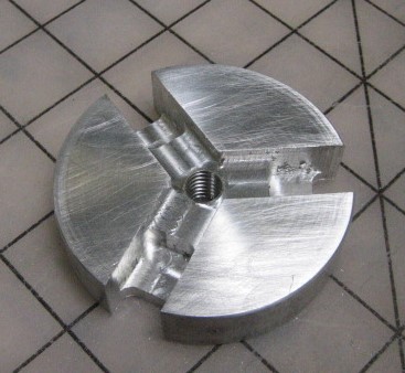
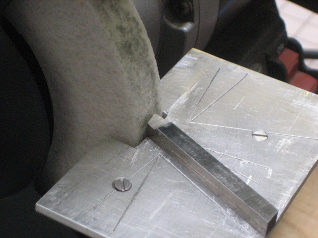
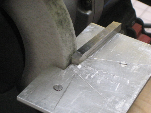
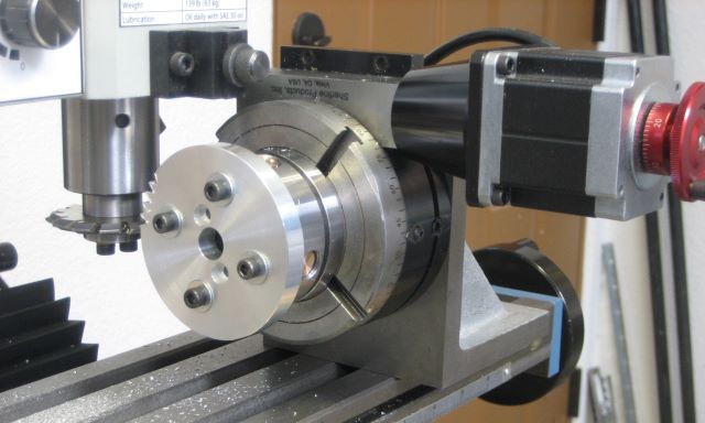
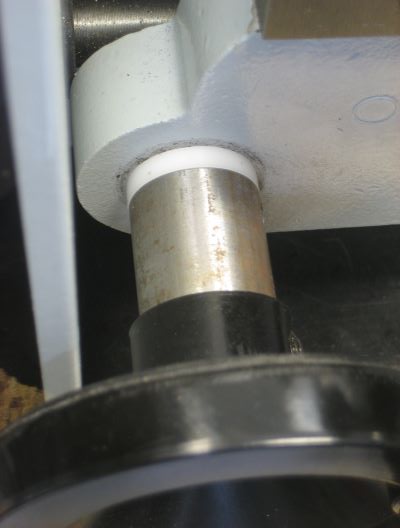
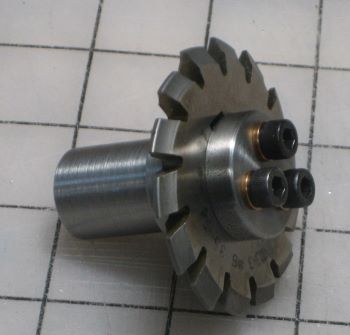
Mod 2: I still needed additional torque from the motor. Since the motor could supply plenty of power (speed times torque), a gearbox was needed. I bought two involute cutters of China source and made a mandrel to hold them.

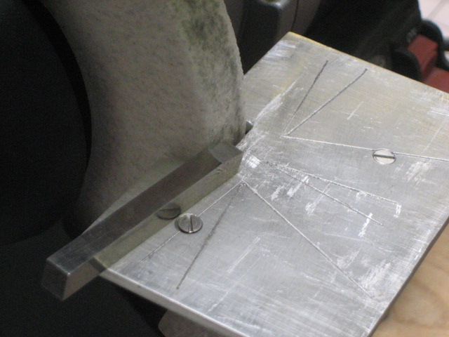
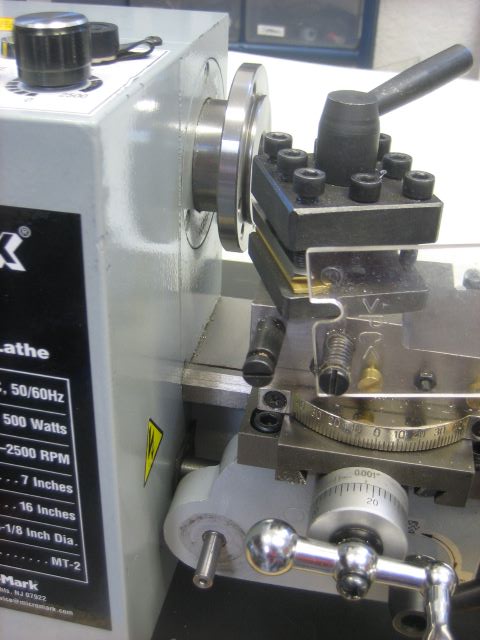
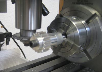
Setup for cutting the 48 tooth output gear:

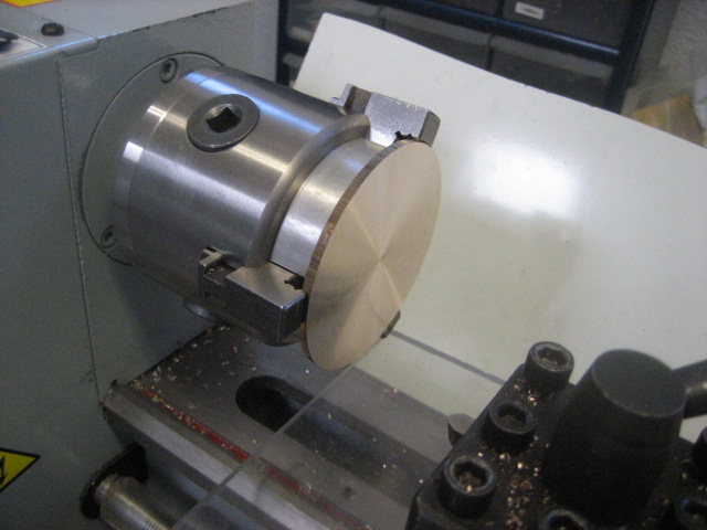
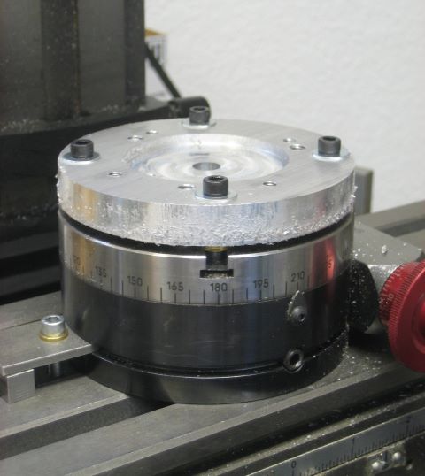
Setup for cutting the 17 tooth pinion:

Both gears grip shafts through shaft collars.

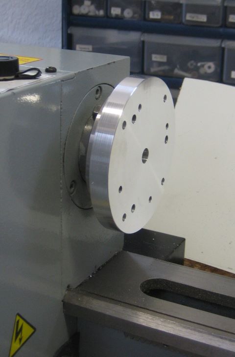
This is the gearbox frame. It is designed for NEMA 34 mounting at both input and output and so can be simply bolted in between motor and crank.

Finally, a different view of the modifications:

I reprogrammed the Arduino chip to give 1100 pulses/sec (was 400) so blade speed is unchanged. With the larger crank torque, I can use the extra weight at the front end of the saw.

Note on saw frame mounting: The Stanley saw frame is bent from an oval steel tube. Bending distorts the oval, making it thicker on the inside of the bend. When the frame is screwed to the two hangar brackets, they will twist as the screws are tightened. This will lock up the linear bearings. I used shim stock at the interface to prevent the twist and preserve free sliding motion.

The poor design choice here was to make the reciprocating frame from the Stanley saw and two hangar brackets (aluminum 3/8 x 1). It takes a lot of attention to keep everything aligned so that the 4 linear bearings do not bind. A better design would be to make this one piece, which would require a 3/8 aluminum plate about 8 x 15 inches. I may pursue this change if I figure out how to profile the aluminum plate.

Update 13 Dec 2019: Problems with binding have continued, so I have replaced the Stanley saw frame with a homemade frame. This keeps the bearings aligned and seems to have solved all problems.


This is working so smoothly that the gear reduction may not be necessary.

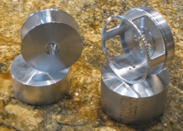
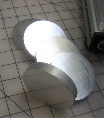
Update 18 Feb 2021: The power hacksaw is providing me with the slabs that I need for ferrule shrinking tools. It is slow; one cut-off from the 2.63 inch diameter bar of 6061 takes somewhat more than 3 hours. But for all this time, operation is unattended.

Slabs are quite clean and square.

Cutting a one inch round bar of 41L40 takes 14 minutes.

Posted in Cutting | Leave a comment

Inefficient Use of Material

I am starting a reel with a winding plate, similar to a “Perfect”. Here are the aluminum parts.

Left: spool, 25 grams from a 233 gram blank (10.7%).
Right: frame, 42 grams from a 391 gram blank (also 10.7%).

Posted in My Reels | Leave a comment

Faceplate for Minilathe

I was working on a new reel design, and realized that several operations would best be done with the parts clamped to a faceplate.

The problem, however, is that on my Minilathe, the carriage cannot travel far enough left to get the toolpost in position. The travel is OK for a part held in a 3 jaw chuck, but not for a part clamped to a thin faceplate. The large handwheel for carriage travel interferes with the box of variable speed drive electronics.
In this picture, you can see that I long ago added an acrylic plate as a chip shield. It also restricts carriage travel, but is no worse than the handwheel.

The first thing that occurred to me was that the electronics box needed to be relocated. It was really stupid of the designer to put it in this position.

The rack and the leadscrew are both capable of moving the carriage far enough left to allow faceplate use, it is only the electronics box restricting travel.

But then I saw that it would be much easier to just move the handwheel.

So I made this extender for the handwheel shaft.

Here the extender is installed.

I made a 4 inch diameter faceplate on my mill.

Here is the faceplate installed and finish turned.

Posted in Fixtures, Turning, Work Holding | 2 Comments

San Juan River

Was at the San Juan yesterday for the first time, did a float trip from Texas Hole to Crusher Hole. That must be the standard route, as there is even a shuttle service to spot the guides’ vehicles and trailers downstream.
It is a tailwater fishery. Water was clear; I have never seen so many trout. They get fat on the abundant midge life coming out of the bottom draw of the dam.

It is bobber fishing over tiny nymphs. I had a “San Juan Slam” of rainbow, cutbow, and brown. Many hookups, many brought in, most of nice size. Guide Scott Warren of Durango CO.

Posted in Fishing | 1 Comment

Alaska

My family took an Inner Passage cruise. Son-in-Law and I used the Juneau day to go fishing. I did not research what to do ahead of time, we just signed up with the Cruise Line standard. Bear Creek Outfitters and guide Sam did a fine job: supplied waders and rods, and tied all knots, etc. Also carted the special items needed for Alaska fishing: satellite phone, bear spray, firearm.

We flew out on a Beaver to Slocum inlet and then slogged our way up the creek.

Sam gave us Clouser Minnows, but of colors that I never saw in Michigan. A “school” of Cutthroats and Dolly Varden readily took these streamers. A little father upstream were Pink Salmon, and they wanted the Clousers also.

Granddaughter clearly does not believe my lie about a big fish.

Posted in Fishing | Leave a comment