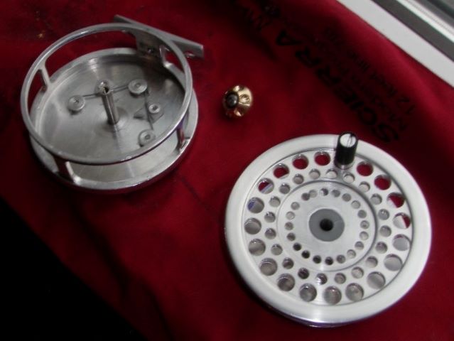
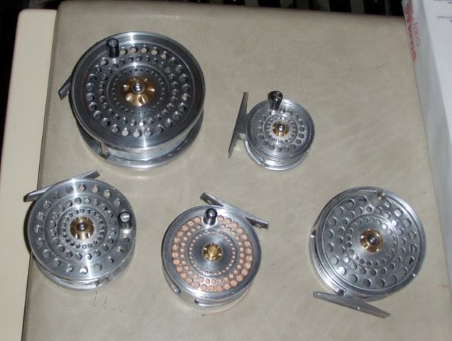
My friend Terry has been experimenting with powder coating for reel finish.

Powder coating is done with a dc supply aiding the attraction of paint to the object. I quizzed Terry about the process, and here is his explanation:
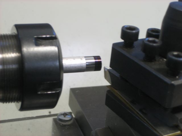
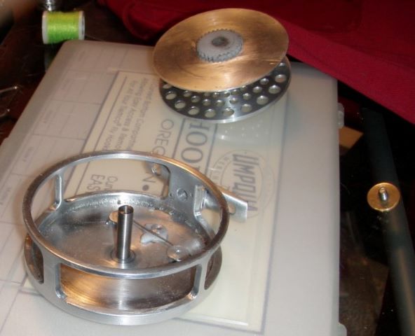
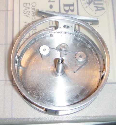
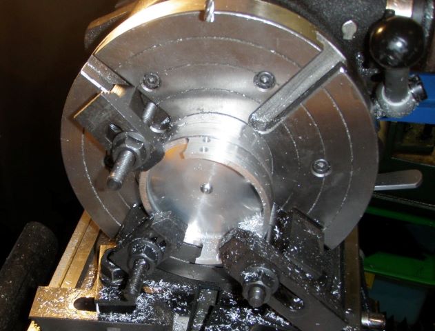
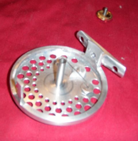
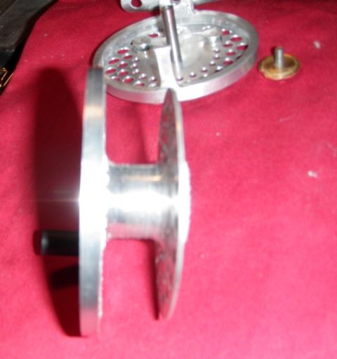
“I bought all of my powder coating equipment from Eastwood . I also bought a small pancake air compressor from them, but I could not get the spray gun to work right with it, so I ended up using my larger Craftsman compressor, which worked really good. You only use about 7 or 8 psi maximum with the gun. For some reason, the pancake compressor could not provide enough air volume at the required pressure to allow the gun to spray the powder properly. I made a small jig that press fits into the hole for the spindle in the frame. It has a 4 inch long 1/4″ diameter spindle and a 3 inch diameter base the is 3/8” thick. Both the base and the spindle are made out of aluminum. Using this spindle, The spindle presses into the back of the frame. I first placed the frame on the floor with the back side up and the spindle and base sticking up. Then I sprayed the back and sides of the frame. Then I very carefully picked up the frame by the jig and the set the base of the jig on the floor. This positioned the frame with the back down and the inside of the frame facing up. This allowed me to easily spray the inside of the frame. The jig also allowed me to turned the frame in either position 360 degrees as required. The ground wire for the electrical system is attached to the spindle just above the base. Once the frame is fully sprayed, then I very carefully picked up the jig with the reel frame on it and placed it in the toaster oven I bought and brought the temperature up to 400 F. Then allowed it to bake for 25 minutes after I seen the powder flash and flow. I also bought a digital remote temperature gun from Eastwood to keep track of the temperature of the part while it was baking.
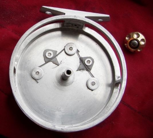
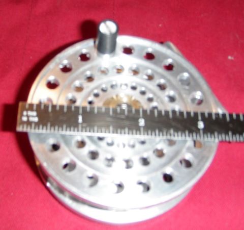
“The thickness of the powder coat is about 0.002″ +/-. The powder coat is really tough, and if your want to remove it, it is really hard to get off. I even tried a steel wire wheel on my Dremel tool and even that barely worked.”

Eastwood is a supplier of equipment for auto work, and I think that powder coat is used for engine parts because it can take high temperatures. Perhaps there is another powder coat source that offers a smaller gun that would work with a small compressor. I searched a bit for guns, but they all look pretty large.