Metal Spinning

This post is about an experiment with an unsatisfactory result. But we learn from failures, perhaps more than from successes.

I am interested in making spool ends for reels by metal spinning. The goal is to make a spun spool end from nickel silver so it can be brazed to the shaft, but my experiment was with aluminum which is supposedly easier to spin.

There is a good on-line article on making a spinning lathe, but since my goal seemed modest (just a small amount of forming) I tried to get by on the cheap by spinning on my Sherline lathe. The conclusion is that even for this simple task the Sherline is not sufficiently rigid or powerful.

My information source was a book from Artisan Ideas, which turned out to be a technical school textbook from 1936. I recommend the book as a record of a disappearing art. It shows what should have been a warning to me: the spinning tools are often 2 or 3 feet long, to get the leverage needed.

Here are the tools that I made (or bought) for my lathe:

From the top: clamping bolt, brass fulcrum, brass clamping washer/pilot, aluminum form or “chuck”, aluminum and nickel disks to be spun, steel tool with hemispherical end. The forming that I wanted was to turn the edge of the disk 90 degrees.

This is the setup. The cardboard box is to be moved forward to serve as a shield from the expected spray of warm lubricant (beeswax) which, in the event, did not happen.

Here is a modification of the setup to move the fulcrum to better position.

Forming the spinning disk takes a larger force than I could apply, given the compliance of the lathe and the length of the tool. I could not turn the edge 90 degrees.

Here are the front and back sides of the partly formed disk.

There was no point in trying the nickel silver disk (.032 thick) since I failed with the aluminum (.040 thick). So I will continue to use machined spool ends.

Update 18 July, 2011
Instructional Materials
Richard Westerfield read my original post on metal spinning and offered to loan some instructional materials. One was a set of DVDs by Terry Tynan.
The other was a CD-rom by James Riser.

I recommend both. Tynan is an expert spinner and shows the techniques to spin many shapes. Riser seems to be more of a DIY amateur who figures out how to get things done. Tynan may forget to mention what he uses for lubricant; Riser will give you a dozen alternatives. Tynan makes his tools by grinding pre-hardened rods; Riser does it by forging.

How would I use this information? Tynan’s 3rd DVD concerns projects done where the lathe is a converted wood lathe. The one he uses looks as if it would handle a 10 or 12 inch diameter wood workpiece. There are just two steps to the conversion: 1) add a C or Bar clamp to the bed to keep the tailstock and toolrest holder from creeping, 2) make a spinner’s toolrest.

I wish that I had taken to trouble to seek out this material before starting my spinning effort; I probably would not have wasted my time. The CD and DVDs are very good and I recommend them to anyone who is serious about spinning. But I need just one spun part, a spool end, and I can machine that.

Posted in Forming | 9 Comments

Brown Drakes


We had Brown Drake emergence on the local river the evenings of June 2 to 4. Lots of bugs in the air and on the water, but little obvious feeding activity by the trout. I fished with John, who reported getting strikes at the moment he was picking his parachute fly up off the water, as it momentarily dipped below. So next year I will tie a emerger version of the drake, probably as a soft hackle.
Last night the spinner falls began. From about 9:15 to 9:45 there were spent wing bugs on the water and active feeding. I was fishing a fly from a local shop and not getting takes; I think the #12 fly was too small. So I switched to a larger fly (12 or 10 long shank)and then got a fish.
The National Weather Service, Climate Prediction Center, reports that the Cooling Degree Days so far for this season are 47, as of June 4.

Posted in Bugs | Leave a comment

Aluminum Raised Pillar Frame

At Classic Reels Forum I saw a reel by E. vom Hofe that I particularly liked, so I am using the photo as a general model for my next reel.
Here is the aluminum frame, with parts tumbled in coarse media (plastic pyramids) but not yet polished with walnut shell and rouge.


I expect the weight to come in at 5.25 oz., and that is with a nickel silver crank, handle pin, and counterweight.

I had hoped to use nickel silver for the spool ends, but that would have entailed a weight penalty of 1.4 oz. So I will use aluminum for these. I intend to make a hollow bronze shaft that is silver soldered from 3 parts. This will save 0.50 oz. over a solid shaft.

The vom Hofe reel appears to have an adjustable drag (knurled knob under the crank) per patent 219328, but I will just make a fixed ratchet and pawl drag.

Update 5 June 2011: Here is the frame after polishing with walnut shell and rouge. It is shiny now, but anodizing will make it less reflective.

Posted in Frame | Leave a comment

Using the Foot Fixture

This post is of interest to anyone who bought my plan set at The Eclectic Angler, and will be making the foot fixture of drawing 1015. I started to use the fixture this morning and went through a “deja vu” episode. When I originally designed the fixture, my intent was to bolt it to the rotary table in its normal position (i.e., flat on the mill table), then turn the mill head so the cutting tool is horizontal. As I found out after making the fixture, the head of my Sherline mill does not move far enough downwards to reach the bottom end of the foot. Had the baseplate of the foot fixture been 1 inch thick instead of 3/4, it would have been OK.

Because I use the fixture infrequently, I got every thing set up before remembering this problem. So then I unbolted all and re-did the setup, but with a “tilting angle table” set at 90 degrees. I have gone through this false start every time I have used the fixture.

Now, the rotation axis for the fixture is horizontal and the mill cutting tool is in its normal vertical orientation. Sherline also sells a rotary table mount that is right angle only, and it would work as well.

The horizontal orientation of the workpiece allows a better view of the machining process, and is probably a better setup.

Posted in Fixtures, Foot, Milling, Work Holding | Leave a comment

Speed Calibration

Sherline lathe or mill speed is set with a knob, but the only indications for the knob are which direction to turn to go faster or slower. I have gotten along with just this for about a year and a half, but when I recently ruined a slitting saw blade, I realized that I needed to be more careful in setting speed.

Industrial speed sensors are available at on-line auctions for much less than industrial prices. I was able to get a Red Lion MP37CA00. This is a magnetic pickup; inside there is a coil and a permanent magnet. It can sense passing objects of steel.

Here is a better picture of the rotor that I made of mild steel. It has 6 teeth so that 100 Hz corresponds to 1000 rpm. The data sheet for the sensor explains proper tooth size. This rotor is 0.72 inch diameter, and was profiled with a 1/8 inch end mill.

This is the setup for calibration. My multimeter measures the frequency.

And here is a calibrated speed dial.

The chart below was abstracted from Sherline instructions.

No more ruined tools? Better part finish?

Posted in Measuring | Leave a comment

Perfection Loop

Yesterday was a beautiful day so I decided to take a long downstream wade in the middle of the afternoon. This was after a morning morel hunt. Before starting out, I put new tippet on my leader. I use a furled leader (Dec. 4, 2010 post to this blog), and have a “Shorb loop” at the end of it. The tippet most easily attachs by a loop-to-loop connection, and for this I want a Perfection Loop on the tippet. I found that I had forgotten how to do this knot (had not tied it since last summer), and had to refer back to a sketch that I made in 1998, after being shown how to tie it by Ed Strauss at Jorgensen’s fly shop in Fort Wayne.

The perfection loop is a well-known knot and many instructions are posted on the web. But seeing an animated cord knotting itself does not make good instruction.

It seems to me that this is the same as the “Bowline knot” once taught at Boy Scouts. There, it was always tied around one’s waist. The procedure was like the animated cord above; nobody could remember how a week later.

Here is a re-draw of my original sketch.

1. Form a loop
2. Pinch the loop, then poke the tag end between the thumb and forefinger
3. Bring the tag end back around under the thumb then pinch it also
4. Slip the loop from over the thumb up through the first loop

There is now a good Youtube video on the process, and it is almost the same as this. The difference is at step 2; he does not poke the tag end through the fingers but just passes it under the first loop. This probably uses up less tippet.

Posted in Line/Knots | Leave a comment

Raised Pillar Rings, all over again

On Feb. 3, 2011 I made a post on the fabrication of raised pillar rings. Now I am working on a new design that needs similar parts, and I am reminded of how demanding it is to get these right. My first plans are now generally available (see post of May 7, 2011, below) and there is a possibility that someone will want to do the raised pillar version of the design. So I thought that it would be be good to go through the steps in excrutiating detail. Here they are, with a recycling of the old pictures.

These instructions assume that your raw material is a slice of 6061 tubing, 3.25 OD and 2.5 ID. It would also be possible to use rectangular bar stock, 5/16 x 3 x 3 long. I use rectangular bar on the new design (aluminum end plate with integral ring) and am likely to post soon on this approach.

You probably won’t want to read this unless you are just about ready to cut some metal. The relevant drawing is 1016.

1. Grip the raw material in your 4 jaw chuck with jaws on the OD. Face off one end on the lathe.

2. Turn the material over in the chuck, and center in very carefully because there is little waste, OD or ID. I get out my “Last Word” indicator for this. The raw tubing isn’t perfectly round, but I can still look for equal needle swings. Face off the other end to proper total length (dimension A, different for front and rear rings).

3. Still on the lathe, turn the 2.540 and 2.600 inner diameters.

4. Now unchuck and move the jaws inwards to grip on the the new 2.600 diameter, from the inside. The ring will be square with the chuck because the ledge at the diameter change will rest on the top of the jaws. Re-center the work using the Last Word.


5. Now move the chucked part to the rotary table on the mill and cut the 2.680 diameter, so that an 0.125 flange is left. My usual procedure is to remove most of the material with the mill and then go back to the lathe to finalize the dimensions. I have had more practice with the lathe and can get better finish and dimensional control. Use a file to round the corner at 2.680 diameter. Work safely and put a wood handle on your file.


6. Back on the mill now, center drill, drill, and counterbore 5 holes. I do the counterbore by plunging a 2 flute end mill of the right diameter. I find that setting angles with the rotary table is quite repeatable and that there is little backlash. So it is OK to center drill 5 times, then change tools and drill 5 times, etc. During the counterbore, my rotary table has a tendency to drift from vibration, so I “lock” its position with a patch of masking tape on the dial skirt.
This is also the time to plunge mill two more hole in the flange, 0.25 diameter, diametrically opposite, and just far enough out that they don’t encroach on the 2.740 diameter that will next be milled. I will give the reason for these in the step 8.


7. Now cut away most of the flange, down to 2.740 diameter. The ring will become flimsy in this process, and would loosen if held in a chuck. So I screw it to a round toolplate; the one in drawing 1014 works fine if five holes (4-40 tap) are added to the face.

8. There are 8 inner radii of 0.125 inch on the periphery. Make these by plunging an 0.25 endmill at the correct positions. Getting the positions exact is the reason for the two extra holes mentioned in step 6. Fasten the tool plate to the rotary table, but don’t tighten the two clamp screws. Mount the ring to the tool plate with 4-40 cap screws, aligning the two holes over the the rotary table clamp screws, and flange up so the flange has clearance from the tool plate. Now position the rotary table so that a #31 drill bit will cleanly descend into one of the five lug holes, and so the rotary table angle is an easily remembered number like 0 or 45 degrees. Use a short drill bit, as a “jobber length” is unlikely to be straight. When aligned, tighten the tool plate clamp screws through the two flange holes, which may require a ball hex driver (depends on the radius that you located the clamp screws). Plunge the 8 holes, noting from the drawing that they are 10.6 degrees away from adjacent lug holes. Radius to the center of these holes is (2.740 + 0.250)/2 = 1.495.

9. Now you can trim the flange. Stay with the 0.25 end mill. I move out to a radius that is larger by 0.010, i.e, to 1.505, and mill in two passes of 0.063 deep each. Then I return to 1.495 radius and clean up the edge with a single full depth pass. Write out a table of limiting angles for each arc and put it where you can see it while working.


Should look like this when done.


10. Milling the small radius around a lug requires the lug to be at the center of the rotary table. My round tool plate was too small to accomodate a second screw, so I made another tool plate of .375 x 1 bar, 3 inches long. Like the round tool plate, it has a brass pin to pilot on the rotary table.

11. Before trying to cut each 0.150 radius arc, trial fit the end mill in the two holes that mark the ends of the arc. This will confirm positioning of the table and show you the angular limits for the arc. The milling pass can be made a little short of these limits, since you do not want to risk hitting the newly cut 2.740 diameter. I make these last arcs in two passes of 0.063 depth each.

12. Touch up minor imperfections with a file.

Posted in Ring | Leave a comment

Reel Plans


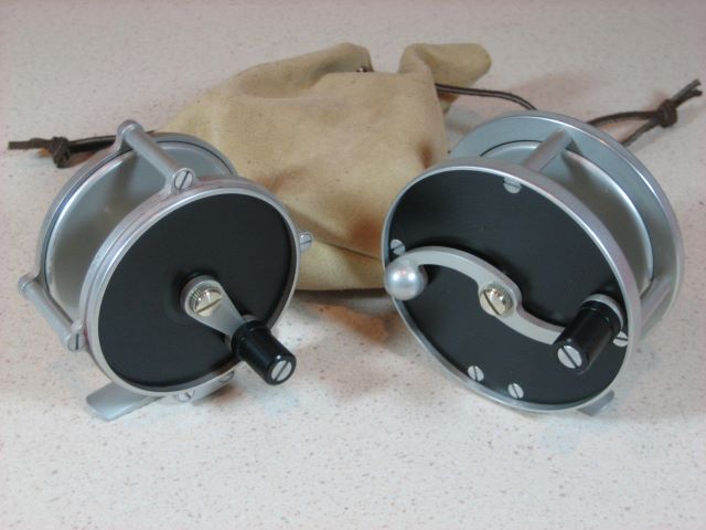
After making the reels shown here, I sat down and redrew my rather ragged looking set of plans. Then I contacted Michael Hackney to see if they would be something to show on his forum Reelsmithing. He was favorable. After a few Email rounds, we settled on making a publication out of the plans. So they can now be purchased at his commercial site, The Eclectic Angler. Just look for Kits, Materials & Books > Books and Plans. The title is “Round and Raised Pillar Reel Plans”.

Update 27 Nov 2014: I see that Michael has moved the plan sales from The Eclectic Angler to Reel Lines Press.

So that you can see what is available, I have put the contents in this post, but at lower resolution than you would get with the booklet at The Eclectic Angler. Here it is:

Construction Notes for Reels 11 and 15
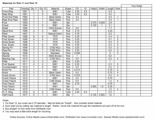
These notes supplement drawings 1000 through 1018.

Two relevant web references are:

A. My blog, http://northbranch reels.wordpress.com. Here you will find much supplementary information.
1. Anodizing (May 4, 2010)
2. Gear Cutting (May 10, 2010)
3. Testing Pawl and Ratchet (May 30, 2010)
4. Overview at Grayrock (June 24, 2010)
5. more on Pawl Wear (Aug. 22, 2010)
6. Loctite Spool Assembly (Aug. 27, 2010)
7. Embarrassing Retraction (Sept. 6, 2010)
8. Milling the Foot (Sept. 28, 2010)
9. Milling the Crank (Oct. 4, 2010)
10. Turning the Counterweight (Oct. 15, 2010)
11. End Plates (Oct. 23, 2010)
12. Spool Ends (Oct. 31, 2010)
13. End Rings (Nov. 7, 2010)
14. more on Pawl Wear (Nov. 16, 2010)
15. Screws (Dec. 14, 2010)
16. Parting (Dec. 19, 2010)
17. Dry Fit (Jan. 13, 2011)
18. Raised Pillar Frame (Feb. 3, 2011)
19. Metal Finishing (Mar. 3, 2011)
20. Anodizing Problem (Mar. 6, 2011)
21. Glamour Pictures (Mar. 22, 2010)
After March 2011, posts start to get into issues with a new design.

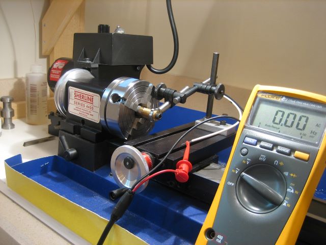
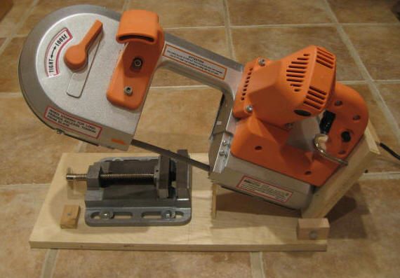
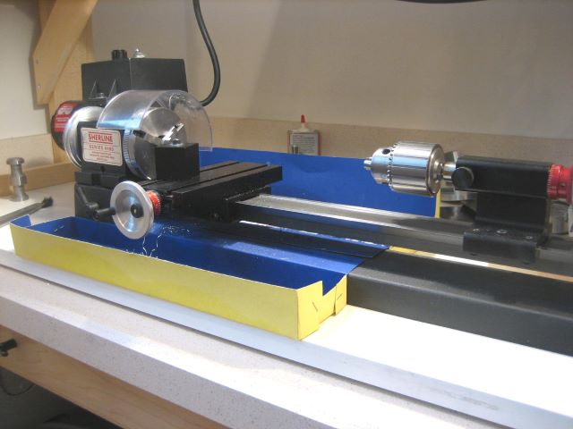
B. An article in Power Fibers on-line magazine for April 2011, “Small Machine Tools for Reel Fabrication”. This article shows the tools that I use. Please read first, as it is highly relevant to what follows here. I reprinted it in my blog on May 6, 2011.

Link to Power Fibers

Disclaimers:
1. I am not promoting Sherline Tools. Sherline just happens to be what I own, and the only machine tools I have used. I am not knowledgeable of the alternatives.
2. The designs here are not reproductions of classic reels. I don’t collect classic reels so I don’t have extensive background on how they were built. I just designed this reel to have a similar general appearance.
3. Because I am a self-taught machinist, I may not know the best way to do everything. But I have a workable method to make the parts for this reel design. I may unknowingly employ some difficult means to do some simple task. If you spot a glaring absurdity, please tell me. Post a comment to the blog.

Why “Reel 11” and “Reel 15”?
I decided to put serial numbers on my reels, and did not want to start with S/N 1. Some potential buyer might think I had never made a reel before (and he would be nearly right). After making a prototype, I decided to tackle a group of 5 reels, and numbered these 11 through 15. So the original prototype became reel 10. Close to the end of machining, I changed reel 15 to a raised pillar design, using most of the same parts as 11-14.

Isn’t it difficult to do this work with such small tools?
It is slow rather than difficult. When your lathe and mill are lightweight and compliant, you are restricted to light cuts on relatively soft materials. So it is not a good economic proposition. I do not recommend Hardy style designs with one piece frame and spool; too much material to remove.

Should I try this if I am a right brain person?
It does involve the ability to concentrate for a long period of time. Basic trigonometry is needed. You might deduce that I am left brained.

What is the advantage of this design?
It has been built five times, as of this writing. So the parts do fit together. Tooling investment is minimal, for a machine shop. Materials have been chosen with consideration for ease of machining. And there are not many other reel plans available for the home shop machinist.

Why don’t the dimensions on these drawings show any tolerances?
I do know something about setting tolerances for the parts of an assembly, but I consider it unnecessary for a “one off” item where one craftsman makes all the parts. He is going to make them fit together. A given part doesn’t have to fit every possible realization of its mating parts. Four of five reels went together for me as first machined, and one needed a washer shim on the shaft.

Notes on the Individual Drawings
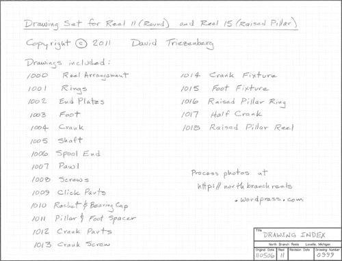
0999, Drawing Index
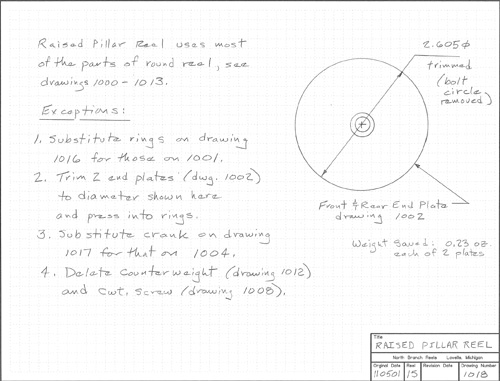
Drawings 1000 through 1013 show the parts needed for Reel 11, a reel with round side plates and an S shaped crank. 1014 and 1015 are fixtures used to make two of the more difficult parts. 1016, 1017, and 1018 show alternate parts/modifications that turn the round reel into a raised pillar reel (Reel 15).
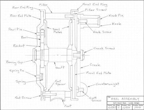

1000 Reel Assembly
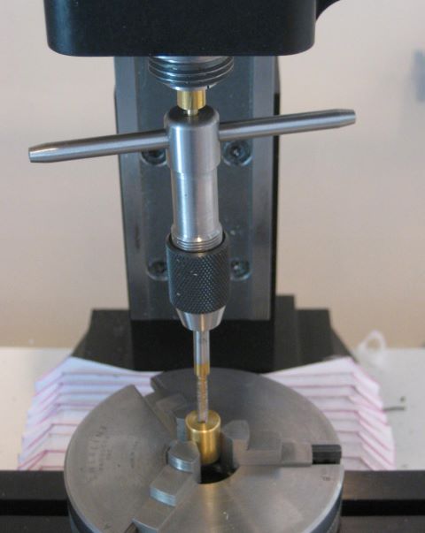
This just shows how all the parts go together. The pawl pin, spring pins, and bearing cap press into the Delrin rear end plate with an interference fit. You will need an arbor press or a bench vise, along with suitable “push tools” (pads, anvils), to put these in place. The spool ends go onto the shaft with Loctite; I went to some effort here to avoid contact of bare metals with different electrochemical potentials. The ratchet pushes onto a portion of the shaft that has been raised by knurling. I find it too difficult to make an interference fit between plain diameters on metals.
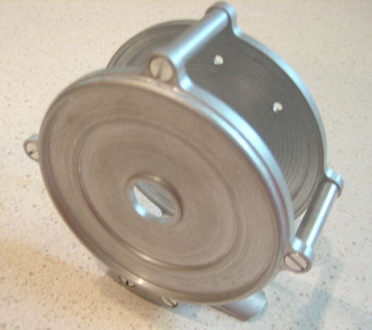
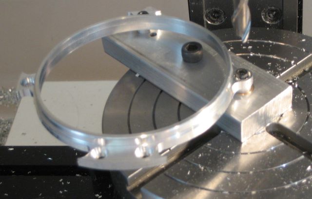
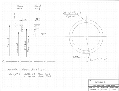

1001 Rings
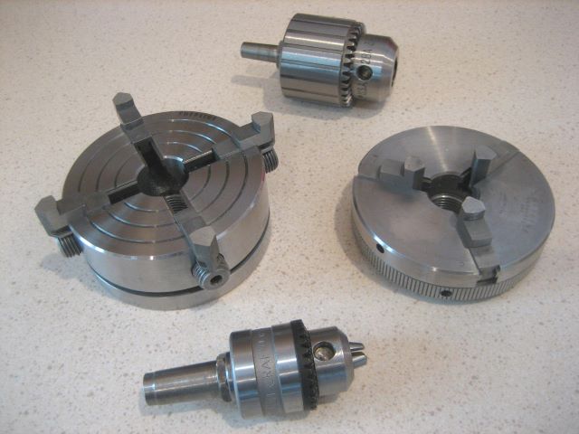
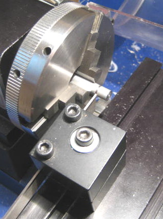
I made these from heavy wall tubing of 3.25 OD, 2.50 ID. Speedy Metals has it. Buy 1 inch cut-offs, which are easy to hold in a 4 jaw chuck while hacksawing narrow rings. See my chuck holding fixture in the Power Fibers article.
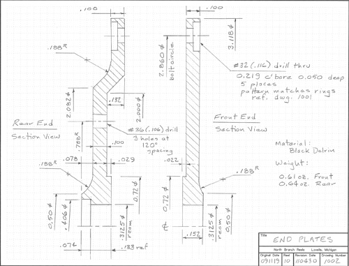
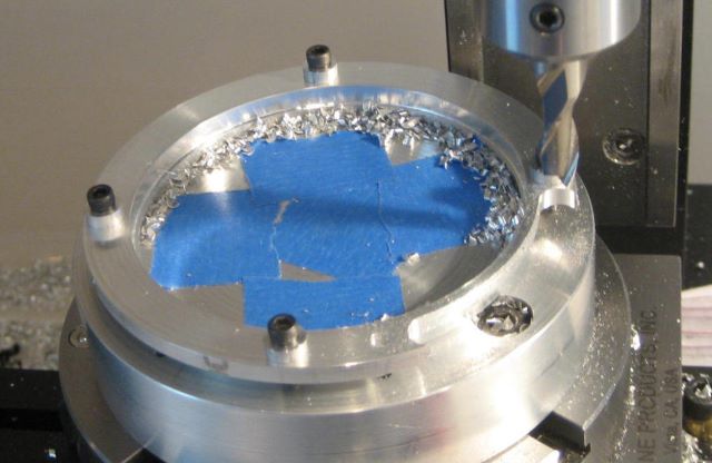
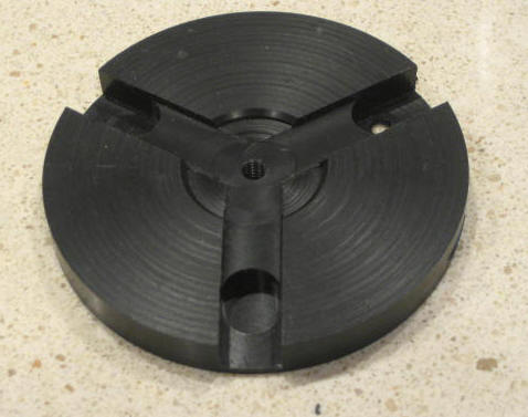

1002 End Plates
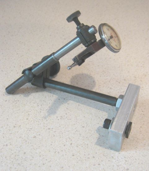
I made these from cut-offs of a 3.5 inch diameter Delrin rod (On Line Metals). But I now think that sheet material would be better starting point. Grip a square of the sheet in the 4 jaw chuck, partly round off the corners with a mill (to gain clearance when you move to the lathe), rough out the rear end plate cavity on the mill, then finish on the lathe. Take care to get the OD and 5/16 bore as concentric as possible. You probably cannot do both with the same chucking, so use your “Last Word” indicator to get centered again when re-chucking.
It is difficult to get a good finish on Delrin. I ended up making a special tool post that holds a 3/8″ diameter carbide cutter with “chip breaker” edge, and then feeding very slowly, using a hand-over-hand (finger-over-finger?) technique on the cross-slide wheel to help maintain constant rotation velocity of the lead screw. That’s why you see 0.188 inside radii in corners of the outward facing surfaces.
In his May 2011 newsletter, Michael Hackney (The Eclectic Angler) explains how to flame polish Delrin. His explanation has the Ring of Truth and probably works, but I have not tried it.


1003 Foot
This is a straightforward mill part except for the curved surfaces. For the bottom, I made a series of passes with a 3/8″ ball end mill, then sanded against a round dowel. The top required a special fixture (drawing 1015). You might make the top surface a cone instead of a cylinder by turning the foot while it is clamped to a mandrel. But it would be an interrupted cut, and that sounds problematical. I used 3/8 x 5/8 bar stock.

Note (29 May2011): Drawing 1003 lacks an important dimension, the overall length of the foot. It is supposed to be 2.50 inches, in accordance with the AFFTA reel foot standard.
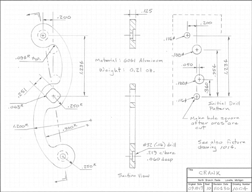
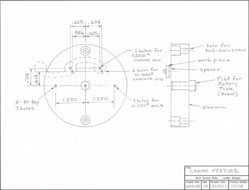

1004 Crank
Here, several circular arcs must meet up on common tangents. It takes some geometry to work this out, but the final solution is the fixture in Drawing 1014. It has enough holes to hold the workpiece in position for the 0.250, 0.900, and 1.200 inch radius arcs. The trick is to first drill 3 holes (0.116) and plunge mill 4 holes (0.188) in 1/8 x 1 bar stock. Then there are points to fasten down the part and good visual references for starting and stopping each arc. The 0.251 square hole is not made until all outside edges are milled. Until that point, it is just an 0.116 drilled hole, which closely fits a 4-40 clamping screw. I put spacer washers between the part and the fixture while milling so I don’t have to cut into the fixture.
When milling the several arcs, I cut them oversize 0.010 in two passes of 0.063 depth each. Then I come back and take off the last 0.010 in a single full depth pass. That way, I can get a smooth finish. My 3/16 milling cutter has 2 flutes.
When making the 0.251 “square ” hole, I first cut it undersize with a 1/8” end mill. Then I take a square section file and hand work it to a close fit to the shaft (which I made first).
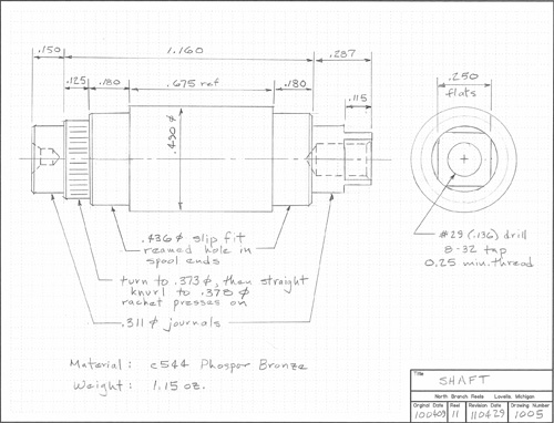

1005 Shaft
This is a straightforward lathe part. I tried to turn it between centers but did not have clearance for my lathe tools. So I held it with a 4 jaw chuck and did one end at a time. I think I got less than 0.001 runout between journals by careful alignment with a “Last Word” indicator.
I used C544 bronze. This material machines freely, is more corrosion resistant than brass, and forms well (for knurling). I could have saved weight with aluminum, but somehow I cannot think of aluminum as a material for shaft journals.
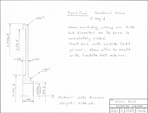
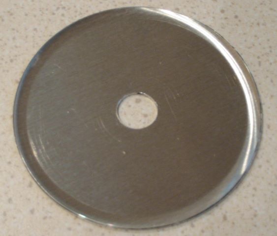
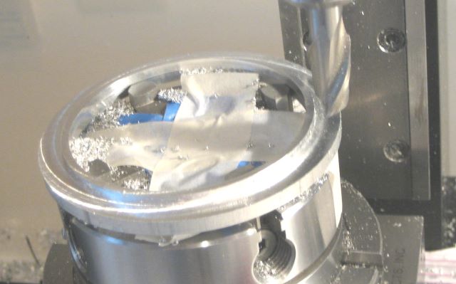
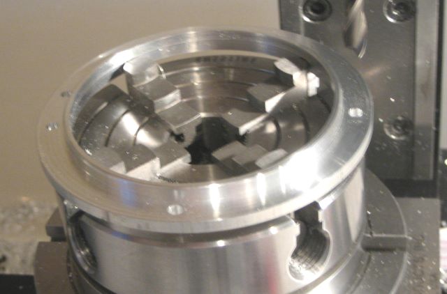

1006 Spool Ends
I used 2.75 inch diameter rod cut-offs. I made the back side recess with the mill, then switched to the lathe. I chucked on the back side 0.75 diameter while making the OD and the 7/16 bore, in order to get best concentricity. Used my 3/8 diameter carbide insert for the 0.188 radius, which is tricky because there is a big squeal if I try to take too wide a chip. I approach the final position of the cutter in steps, first from one direction and then from another.
For the 0.094 radius, I cut a 45 degree corner off and then finished with a file. Sherline sells a compound slide for making angle cuts on the lathe, but I don’t find it very useful because it doesn’t seem to hold a HSS lathe tool at the proper angle. Instead, I rotate the headstock to a 45 degree angle.
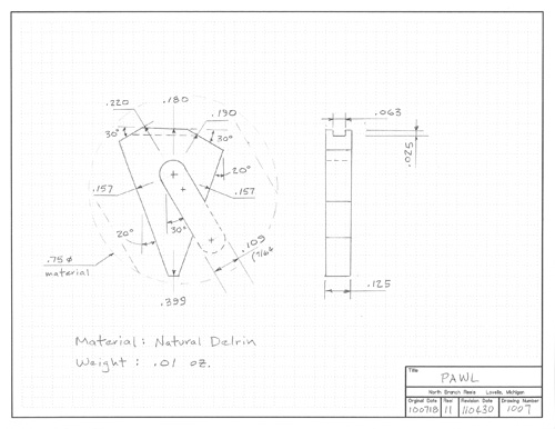
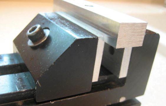

1007 Pawl
You will find that a metal pawl is too loud. Delrin appears to be durable; see my posts in the blog. The shape is an irregular hexagon. I have made it from cut-offs of an 0.75 or 1.00 inch diameter rod. Face the material to 0.125 thickness, make flats on opposite sides and grip in a vise with rabbeted jaws (see the Power Fibers article). Now mill the 7/64 groove, which closely fits a 4-40 screw. Then fasten to the top of a post that has been carefully centered in the 4 jaw chuck, which is in turn on the rotary table. The six sides of the hexagon are all dimensioned from the center of rotation, which is exactly what you need to mill the outline in 6 quick passes.
Another reasonable starting point is 1/8 inch sheet material.
To help retain the spring, a groove is cut on the back.
The two sides cut at 0.190 and 0.220 radius determine the difference between winding in and paying out drag. The pawl can be flipped to change from RHW to LHW.

Update 20 May 2013: Engineering student Keenan has modeled all these parts with Solidworks, and on this drawing he discovered an error. The distance to the long flat should be 0.147 rather than 0.157 inch. Hats off to Keenan.
Even with the wrong dimension, the reel reverses direction with no jam, as the pawl rides its pin on a slot.
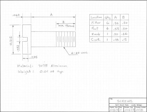

1008 Screws
Maybe I am too cautious about electrochemical corrosion, but I didn’t want to put stainless steel screws into an aluminum frame. So I made the several screws. Used a round threading die, for which Sherline sells a die holder to fit the Morse 0 taper in the lathe tailstock. Many details are in one of my blog posts.
A benefit of making your own screws is that you get exactly the length that you would like to have.
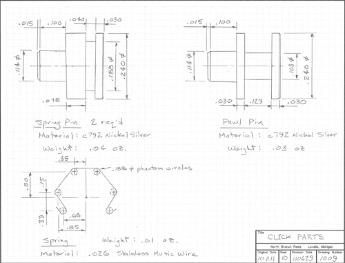

1009 Click Parts
Two spring pins have an 0.040 wide groove made with the Sherline parting tool. The 0.129 groove in the pawl post was also made with this tool by combining several cuts.
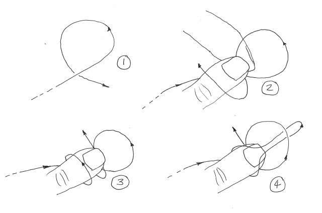
The spring wire is bent using round jawed wire pliers. Here is one task where a full size layout of the part is handy.


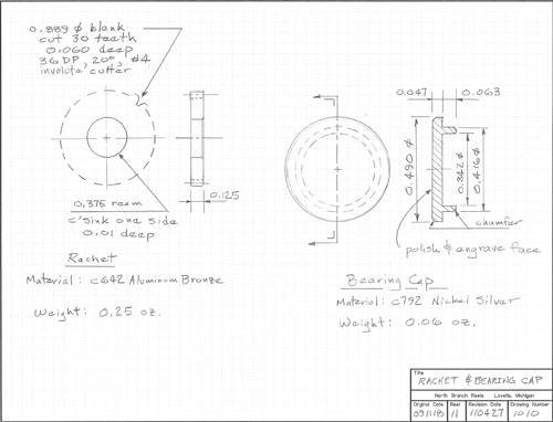
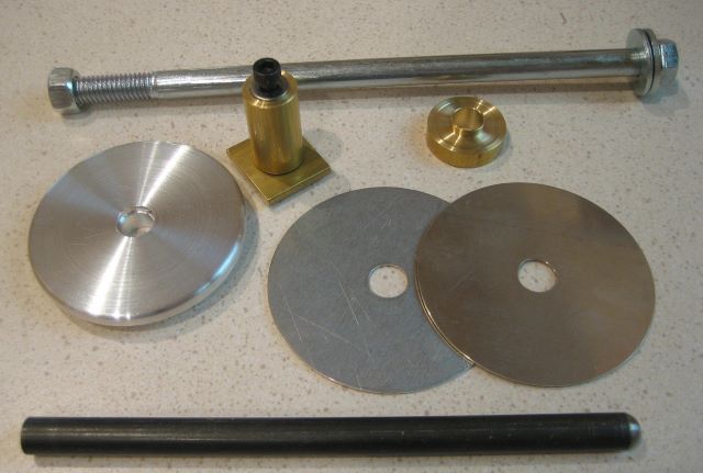
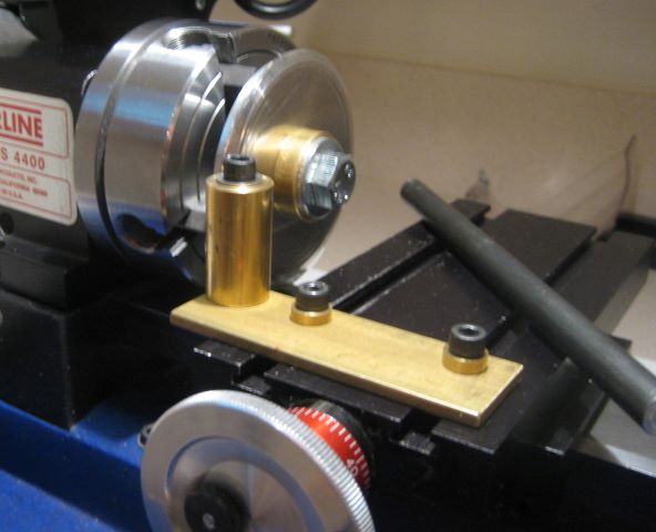
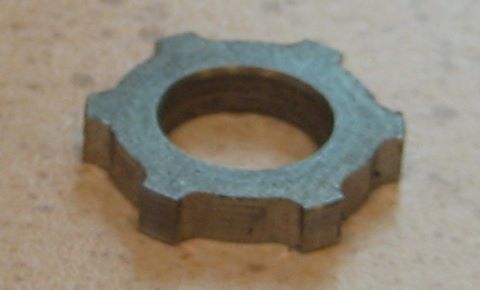
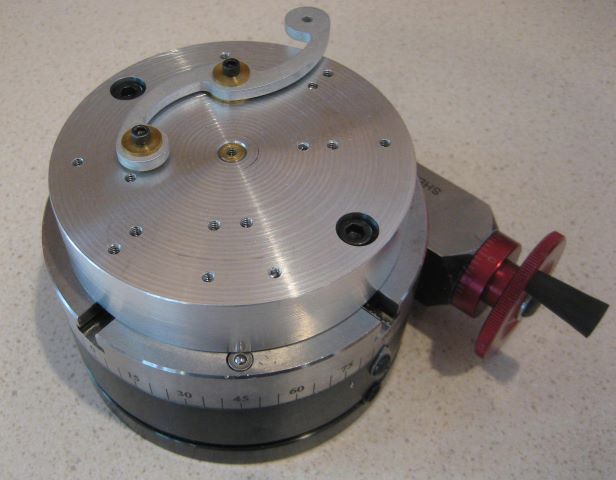
1010 Ratchet and Bearing Cap
The ratchet is C642 bronze, which is relatively hard but still machineable. Actually, all bronzes have a range of hardness that depends on the amount of work hardening. I was reminded of this while facing off blanks for the ratchet, when a carbide tool that had been cutting suddenly started skating across the face.
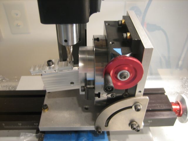
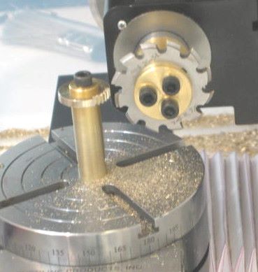
I cut the teeth with a 36 DP, 20 degree pressure angle involute gear cutter. I bought this as a clearance item from Wholesale Tool (http://wttool.com/), not realizing that it was rare. It now appears to me that involute cutters based on the DP system are normally 14.5 degree, while those on the module system are normally 20 degree. So you may not be able to find the same cutter that I used.
I think that there will be no problem cutting these teeth with a 14.5 degree cutter, even though I designed the pawl to look like a rack tooth of 20 degree pressure angle. The pawl tip goes down between two ratchet teeth only momentarily when the spool is reversing direction. Most of the time it is bouncing against the sharp corners at the tips of the ratchet teeth. When the spool does reverse direction, this pawl can ride upwards, away from mesh, because of its slot.
To reduce pawl contact stress, it would be a good idea to slightly round the corners of the ratchet teeth with a file.
While cutting ratchet teeth, I hold the cutter on a homemade brass arbor. The photo of this was mistakenly left out of the article in Power Fibers, but I restored it when publishing the same article in my blog.
Involute cutters are made in sets of 8, each covering a different range of tooth number. No need to get the one for 30 teeth. One meant for fewer teeth will be fine; it will round the teeth more. We aren’t really making gears, after all.

The bearing cap is a decorative part. I had a jeweler engrave its polished face with the serial number.


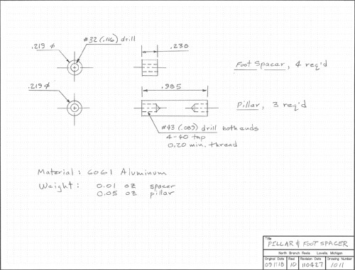
1011 Pillar & Foot Spacer
Not much to say here.
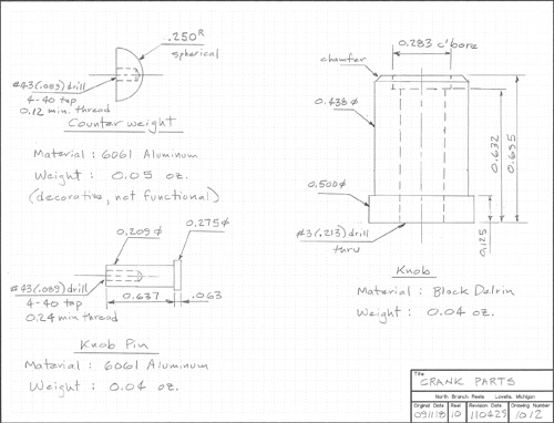

1012 Crank Parts
The decorative counterweight has a spherical surface, produced by mounting a lathe tool post on the mill’s rotary table. A photo that tells the story is among my blog entries. The knob and its pin are straightforward lathe parts.
When I originally designed these parts, I thought that the pin and counterweight would be brass. Had they remained brass, the counterweight would balance the knob and pin. In aluminum, there is no longer balance, but it is not something that I notice while fishing. A larger counterweight would restore exact balance.
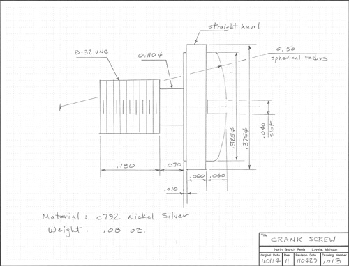

1013 Crank Screw
This is another conventional lathe part, except for the spherical shape of the head, which was produced in the same manner as was the counterweight.


1014 Crank Fixture
Sometimes making the fixture is more challenging than making the parts. See if you can solve the geometry problem of locating the screw-down holes.
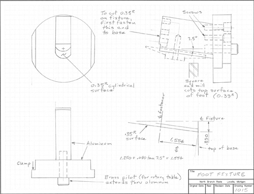
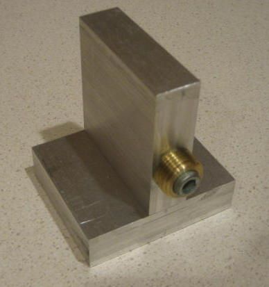
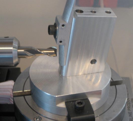

1015 Foot Fixture
This fixture holds the foot at a 7.5 degree angle while the convex top of the foot is milled. One problem in making this is to cut the 0.35 inch radius cylindrical surface that the foot will sit on. The solution is to bolt the upright part upon the base by its other end, then mill that cylinder as you would mill that on the foot itself.


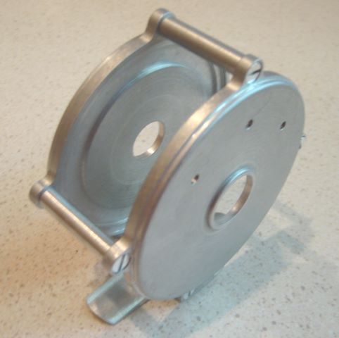
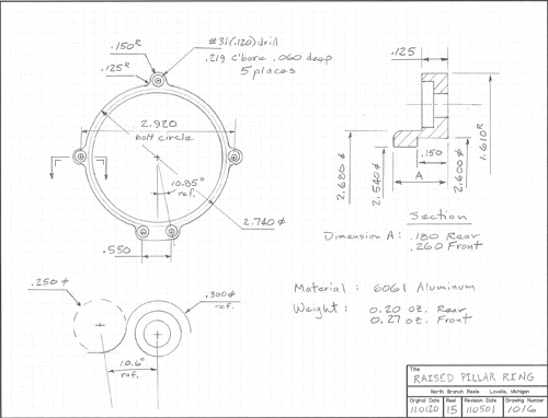
1016 Raised Pillar Ring
This design can be made from the same hollow tube used for the round rings, but it is tight fit. Raw material should be centered when first chucked. I have already devoted one blog post to making this part. A new design under consideration is very similar, and may generate another post. As for the S shaped crank, take the last 0.010 off the edges with a single full depth pass of the mill.
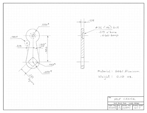

1017 Half Crank
After the S-Crank, this one is easy. Again, cut the “square” hole after the outside is profiled.


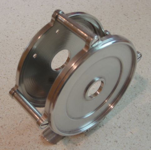
1018 Raised Pillar Reel
End plates smaller than those of the round reel are pressed into the rings. Make a suitable “push tools” for your press or vise from disks of wood.

A word on finishing the parts
One blog entry is on the use of a vibratory finisher. This is not money well spent when you are making reels one at a time. Instead, get several grades of wet/dry sandpaper. A good way to use this is to super glue little patches onto popsicle or tongue depressor sticks, then apply a little lightweight oil while sanding.

Machining with Coolants
A desktop lathe or mill doesn’t have the horsepower needed to heat up the parts. I do not use coolants or lubricants while cutting, except for a drop of light oil when drilling and tapping.

Posted in Documents, My Reels, Plans | 6 Comments

Two More Plastics for Pawls

Someone brought Ertalyte and Ertalyte TX to my attention as possible materials for pawls. The data sheet properties looked promising, so I bought a small quantity of each and made pawls. I tested these on the low speed tester, as before.

But the result was disappointing. Until I find a pawl design that is quiet enough that I can use metal, I am sticking with Delrin.
I am starting to wonder if my pawls are just too big. If that is the problem, then the new pawl design (April 11, 2011) is a step in the wrong direction.

Posted in Materials, Pawl, Testing | Leave a comment

Full Text of Article in “Power Fibers”

Editor Todd Talsma of Power Fibers gave me permission to print my article here as well. Since the April 2011 issue of the magazine is available on-line (and free) for just 3 months, this seems like a good idea. I still advise you to check out the magazine; it is full of good information. Here is the link. And following is the article.

Small Machine Tools for Reel Fabrication

Design

The reels I make bear a general resemblance to classic reels by Vom Hofe and others, but employ modern materials like Delrin and aluminum. Making the parts requires machine tools, lathe and mill. This article is about the tools and accessories that I have found useful for this work, and is written to inform others who, like myself, have no previous experience with machining.
Careful and complete design is an important part of this work. You should not order raw material until you have drawn all parts in detail because oversize raw material means wasted time and expense. This is in contrast to bamboo rod manufacture, wherein securing a supply of cane is perhaps the first step. If you are already familiar with a CAD program, then use it to create the design. But CAD has a steep learning curve that I have been unable to surmount. Pencil lead and cross grid paper are my major design tools. I know of no source for plans; you must be ready to create your own. You might start by disassembling and measuring some favorite classic reel.
When you draw a part, also take time to list the sequence of chuckings and clampings that you will use to make it. If a part has to be re-chucked to work on the other side, figure out how you will get it adequately centered. This will help define the custom fixtures that you will need to make the part, and will reveal design problems.
Anyone with limited metalworking experience should read some instructional books first. I recommend “The Home Machininst’s Handbook” by Doug Briney (TAB Books) and “Tabletop Machining” by Joe Martin. Both of these focus on the small mills and lathes made by Sherline Products, Inc.

Power Tools

A power hacksaw is a practical necessity. Most raw material from on-line sources comes in 12 inch lengths and must first be cut to working size. For larger size metal bars and rods, some suppliers offer a cut-off service. Using a hand powered hacksaw is an unrewarding task, and I find it difficult to make square cuts. My power hacksaw is a handheld unit from Harbor Freight, mounted on a pivoting plywood frame. It is large enough to cut 3.5 inch diameter rod.


My lathe is made by Sherline. Many parts are aluminum, which is more compliant than cast iron or steel, but overall the tool is adequate to work soft metals and plastic. The spindle center is 1.8 inches above the bed and 0.9 inches above the cross slide. Short items (rings, side plates) of up to 2.9 inch diameter can be turned when the chuck is gripping the O.D. When a larger part must be turned, there is a riser block that can be inserted under the headstock, gaining another 1.25 inches of clearance. Ring O.D. for my reels is about 3.1 inches. The headstock can be turned at an angle to the lathe bed, allowing cuts that would require a “compound feed” on a larger lathe. On either side of the lathe base, you can see cardboard trays that capture most of the machining debris.


Sherline lathes are offered with 8 and 17 inch bed length. Although reel parts are short, I recommend the longer bed because it allows use of long reamers to make precise hole diameters.
This lathe uses a D.C. brush type motor, and so has a simple electronic speed control for infinitely variable speed. Power is from a 120 volt outlet.


The mill (also Sherline) has just X, Y, and Z movements; I think this is adequate for most reel work, when combined with the rotary table accessory. Mills with more axes are also available. This mill uses the same headstock as the lathe. It is possible to buy just the X,Y,Z frame and share one headstock with the lathe. I keep the mill inside a large tote so that chips are contained. Access to the handwheels is through holes fitted with cover flaps.
Both my lathe and mill are equipped with the more expensive handwheels that allow zero reset. This helps avoid errors from arithmetic mistakes.


An advantage of these compact tools is that my whole machine shop is located in a 4 foot wide by 2 foot deep space in the home utility room. I sit to run the lathe and stand to operate the mill. The hacksaw, when in use, sits on a garage workbench.
Regardless of Sherline claims, I don’t think that I would try machining at the dining room table.
Those of you with spacious rod shops, heavy power wiring, and unlimited funds may want to consider larger equipment. My point here is that reel work can be done with low-end tools.

Main Accessories

Three jaw and four jaw chucks hold work. They both have reversible jaws for gripping large diameters.
On the 3 jaw chuck, all jaws are simultaneously positioned by a spiral grooved plate. Work O.D. is typically a few thousandths off center, but this makes no difference for all the cuts that you can make without re-chucking. The 3 jaw chuck is used mostly on the lathe, but a simple adapter allows it to be fastened to the mill table.
The 4 jaw chuck has independently positioned jaws, so it can hold shapes other than round. Round work can be precisely centered (to a previously cut diameter) with the aid of an indicator. This chuck is equally useful on the lathe and on the mill, and is particularly good for items that need both lathe and mill work, as it can be switched between the two without re-chucking.
The other two chucks are Jacobs design and typically hold tools such as drills. I use the 1/4 inch chuck when I want to drill with the mill and I keep the 3/8 chuck on the tailstock of the lathe for drilling, reaming, and tapping. These fit to the headstock and tailstock with Morse taper adapters.


The rotary table accessory provides the important (for reel work) 4th axis of motion for the mill. I use it when preparing lathe blanks for rings, side plates, and spool ends; when cutting ratchet teeth; when cutting the arcs of an S-shaped crank; when forming the convex surface of a reel foot; when drilling pillar holes in endplates and rings; and for many other tasks.


The milling vise holds rectangular work such as the blanks for feet, cranks, and pawls. I recommend replacing the steel jaws with non-marring aluminum jaws (homemade). A rabbet at the top edge of the jaws makes it easy to position the work piece. Close the vise on the newly made jaws and cut both rabbets with one pass of a square end mill.

Secondary Accessories
I rated several accessories as “main” because I could not imagine a way to proceed without them. The following I consider “secondary” because you could create your reel design in such a way that they would not be needed.


A cut-off blade, or parting tool, allows you to cut a nearly finished part off the end of a long rod. This is useful when the part is too small to be held by a chuck, for example a screw. You can chuck on the excess rod while making the part. The headstock spindle is hollow, providing space for the excess.


Knurls work by pressing hardened dies into work being rotated by the lathe headstock. They can be decorative, but an important function is making practical press fits. If you want to press a ratchet wheel onto a shaft, you will find it difficult to make the the O.D. of the shaft accurate enough to properly fit the reamed hole in the ratchet. But if you machine the shaft with a few thousandths clearance and then knurl to a larger diameter, pressing is easy.


Sherline makes a thread cutting accessory, but it is expensive and clumsy to use. If you need to make small threads for screws, just get the tailstock mounted die holder. Threading will be even easier with a homemade crank that clamps to the outboard end of the headstock spindle.
I do have the threading tool, and I use it mainly to make larger threads for tooling. For example, the rotary table has a 3/8-16 thread below the center pilot. The spindle nose has a 3/4-16 external thread.

Many other accessories are available, but these are the ones I use.

Measuring Tools and Set-up Aides

A standard 6 inch dial caliper is good for measurements to 0.001 inch, and should always be ready at hand. The handwheels of of the lathe and mill are marked with 0.001 increments, but compliance in the frames and backlash in the handwheels make measurement feedback critical.
A micrometer has a vernier scale that provides readings to 0.0001 inch. Also, the square jaws automatically align the instrument square to the dimension measured, giving you extra assurance of an accurate measurement.
Gauge pins are made to precise diameters. I use them to “calibrate” my micrometer readings.
I often use a strip of 0.001 thick shim stock as a feeler gauge when making set-ups.
A square is useful to quickly align the vise or the rotary table to the mill.
An edge finder with 0.375 shaft fits in the end mill holder. It visually indicates contact with the edge of a workpiece or fixture. I use it most frequently to find the center of my rotary table.


Plunger rod indicators are common today, but I like the old fashioned lever type (Starrett “Last Word”). It is great for adjusting the 4 jaw chuck to center on a previously cut diameter. Here you see it on a home made base. Magnetic bases are not much use on an aluminum lathe.

Custom Fixtures
So far I have discussed what you can buy. But more interesting are the tools that you can make, once you own a lathe and mill.


Custom size washers and spacers are often needed when clamping workpieces.


The common tap wrench has a little hole at the top end. You can make a pin to slip fit this hole, and hold the pin in a collet or chuck. This will keep the tap wrench square with the work. No more broken taps!


Aluminum tool plates are used to clamp work that will be profiled with the mill. This round one fits my rotary table. A brass pin pilots on the center hole of the rotary table.


Here a brass arbor is holding a ratchet blank while teeth are cut. It is tall because the mill headstock vertical travel is limited. Also note the homemade brass arbor for the milling cutter.


My Delrin side plates are about 0.10 thick, and have to be held on the tips of the chuck jaws when being faced. A spacer is needed to set the work parallel to the chuck face, and to stop flexure from cutting forces. This one has clearance grooves for the chuck jaws.


This fixture lets me use the 4 jaw chuck as a vise while hacksawing large stock. The base is clamped by the saw’s vise and the chuck threads onto the brass part.


The top surface of a reel foot is convex. Some cut this on a lathe, clamping the part to a mandrel. The surface produced is then a cone. I decided that I wanted it to be a cylinder instead (the AFFTA reel foot standard is not definite on this point), and so made this fixture to fit my rotary table. The convex surface is developed by multiple passes of a square end mill.


Collets and other tools fit the Morse taper in the headstock of the lathe/mill. You can unlock the taper by striking the loosened draw bolt with a hammer, but this is not good for headstock bearings. Instead, get a shaft collar and leave it clamped to the spindle extention. A simple homemade gear puller then allows quick, non-impact unlocking.

Frequently Used Cutting Tools
I have managed to buy many more cutting tools than I really use. Here are ones that I frequently use. This selection is highly specific to the reel design that I am producing.

A 3/8 square end mill for making ring and spool end blanks (which are then turned by the lathe). Also for several operations in making the foot.
A 3/8 ball end mill to cut the concave surface on the bottom of the foot, by multiple passes.
A 7/32 square end mill to counterbore the screw holes in the end plates.
A 3/16 square end mill to profile the crank, which has several 3/32 inside radii.
A 7/64 square end mill to make the slot in the pawl. This slot closely fits a 4-40 machine screw, which clamps the pawl while it is profiled.
A 1/16 square end mill to make a spring retaining groove across the back of the pawl.


Right cutting, left cutting, and boring bits for the lathe.
A special Sherline tool post that holds a carbide insert.
Lathe parting blade with holder.


Reamers for bores in the spool ends, ratchet, and end plates.
Center drill.
Countersink.
Short length drill bits for clearance holes and tap pilot holes of common screw sizes. Short length helps with the limited Z travel of the mill.
A drll bit large enough to get the boring tool started.
Taps, die.

An earlier picture shows a 36 DP involute gear cutter, used for ratchet teeth.

Web References
Functional and attractive reels can be made without machine tools, see http://www.reelsmithing.com/
For beautiful and inspiring work, see the “Rod and Reel Maker’s Forum” at http://classicflyrodforum.com/forum/viewforum.php?f=93

Posted in Articles, Documents, Tools | 2 Comments