
On Feb. 3, 2011 I made a post on the fabrication of raised pillar rings. Now I am working on a new design that needs similar parts, and I am reminded of how demanding it is to get these right. My first plans are now generally available (see post of May 7, 2011, below) and there is a possibility that someone will want to do the raised pillar version of the design. So I thought that it would be be good to go through the steps in excrutiating detail. Here they are, with a recycling of the old pictures.
These instructions assume that your raw material is a slice of 6061 tubing, 3.25 OD and 2.5 ID. It would also be possible to use rectangular bar stock, 5/16 x 3 x 3 long. I use rectangular bar on the new design (aluminum end plate with integral ring) and am likely to post soon on this approach.
You probably won’t want to read this unless you are just about ready to cut some metal. The relevant drawing is 1016.
1. Grip the raw material in your 4 jaw chuck with jaws on the OD. Face off one end on the lathe.
2. Turn the material over in the chuck, and center in very carefully because there is little waste, OD or ID. I get out my “Last Word” indicator for this. The raw tubing isn’t perfectly round, but I can still look for equal needle swings. Face off the other end to proper total length (dimension A, different for front and rear rings).
3. Still on the lathe, turn the 2.540 and 2.600 inner diameters.
4. Now unchuck and move the jaws inwards to grip on the the new 2.600 diameter, from the inside. The ring will be square with the chuck because the ledge at the diameter change will rest on the top of the jaws. Re-center the work using the Last Word.
5. Now move the chucked part to the rotary table on the mill and cut the 2.680 diameter, so that an 0.125 flange is left. My usual procedure is to remove most of the material with the mill and then go back to the lathe to finalize the dimensions. I have had more practice with the lathe and can get better finish and dimensional control. Use a file to round the corner at 2.680 diameter. Work safely and put a wood handle on your file.
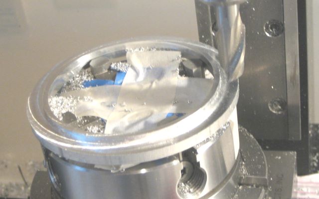
6. Back on the mill now, center drill, drill, and counterbore 5 holes. I do the counterbore by plunging a 2 flute end mill of the right diameter. I find that setting angles with the rotary table is quite repeatable and that there is little backlash. So it is OK to center drill 5 times, then change tools and drill 5 times, etc. During the counterbore, my rotary table has a tendency to drift from vibration, so I “lock” its position with a patch of masking tape on the dial skirt.
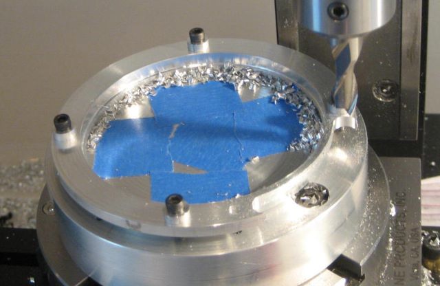
This is also the time to plunge mill two more hole in the flange, 0.25 diameter, diametrically opposite, and just far enough out that they don’t encroach on the 2.740 diameter that will next be milled. I will give the reason for these in the step 8.
7. Now cut away most of the flange, down to 2.740 diameter. The ring will become flimsy in this process, and would loosen if held in a chuck. So I screw it to a round toolplate; the one in drawing 1014 works fine if five holes (4-40 tap) are added to the face.
8. There are 8 inner radii of 0.125 inch on the periphery. Make these by plunging an 0.25 endmill at the correct positions. Getting the positions exact is the reason for the two extra holes mentioned in step 6. Fasten the tool plate to the rotary table, but don’t tighten the two clamp screws. Mount the ring to the tool plate with 4-40 cap screws, aligning the two holes over the the rotary table clamp screws, and flange up so the flange has clearance from the tool plate. Now position the rotary table so that a #31 drill bit will cleanly descend into one of the five lug holes, and so the rotary table angle is an easily remembered number like 0 or 45 degrees. Use a short drill bit, as a “jobber length” is unlikely to be straight. When aligned, tighten the tool plate clamp screws through the two flange holes, which may require a ball hex driver (depends on the radius that you located the clamp screws). Plunge the 8 holes, noting from the drawing that they are 10.6 degrees away from adjacent lug holes. Radius to the center of these holes is (2.740 + 0.250)/2 = 1.495.
9. Now you can trim the flange. Stay with the 0.25 end mill. I move out to a radius that is larger by 0.010, i.e, to 1.505, and mill in two passes of 0.063 deep each. Then I return to 1.495 radius and clean up the edge with a single full depth pass. Write out a table of limiting angles for each arc and put it where you can see it while working.

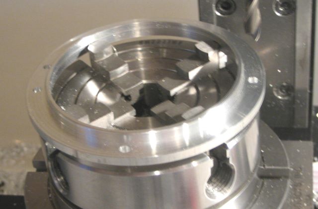
Should look like this when done.
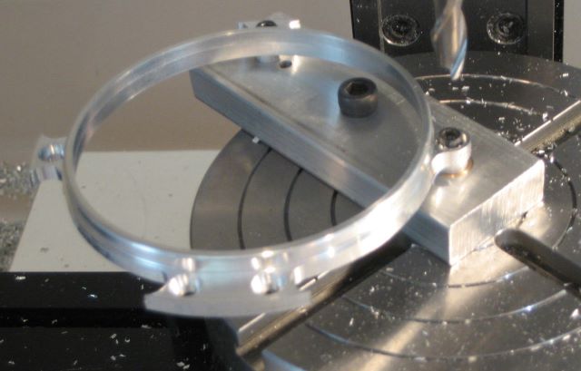
10. Milling the small radius around a lug requires the lug to be at the center of the rotary table. My round tool plate was too small to accomodate a second screw, so I made another tool plate of .375 x 1 bar, 3 inches long. Like the round tool plate, it has a brass pin to pilot on the rotary table.
11. Before trying to cut each 0.150 radius arc, trial fit the end mill in the two holes that mark the ends of the arc. This will confirm positioning of the table and show you the angular limits for the arc. The milling pass can be made a little short of these limits, since you do not want to risk hitting the newly cut 2.740 diameter. I make these last arcs in two passes of 0.063 depth each.
12. Touch up minor imperfections with a file.
