The July 2012 issue of Power Fibers contains an article that I wrote on anodizing.
For the next 3 months, you can download the issue and read the article here. Much of the material is a re-hash of posts on this blog, but there are some new pictures.
Update 10 Oct 2012: A new issue of Power Fibers will be out this month, and my article will no longer be available without a subscription. Below is the entire article.
Since I submitted the article to Power Fibers, I have made advances:
1. A water cooled cathode makes temperature control much easier (this blog, 22 Aug 2012).
2. Small scale electrolytic coloring (this blog, 24 Aug 2012).
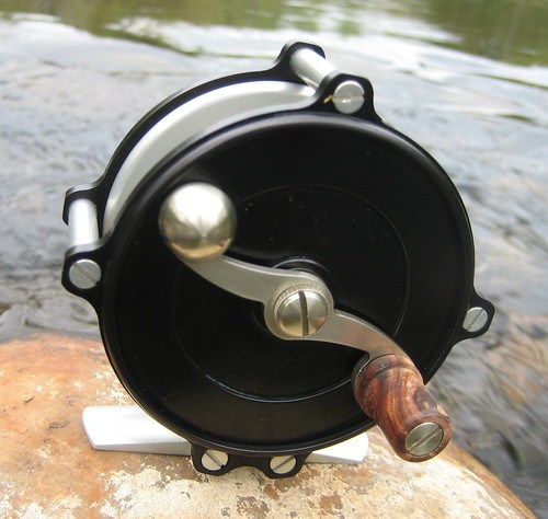
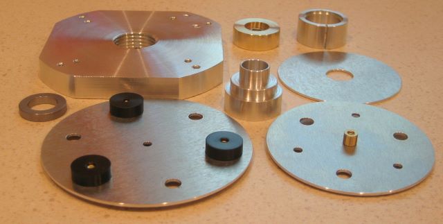
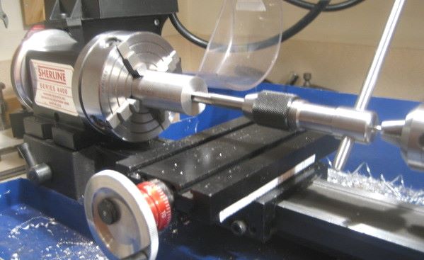
I have been making fly reels on “table top” machine tools. To achieve an acceptably low weight, many of the parts are aluminum. Other home shop reel makers often choose to leave their aluminum parts unfinished, allowing the aluminum to acquire a “patina” of natural oxides over time. I choose to anodize, which is also an oxide coating, but a thicker and more protective one. This gives me control of the reel appearance from the outset. Figure 1 is a reel with an clear anodize finish.

Figure 1 – A reel with clear anodize finish.
Anodize coatings can also be dyed, allowing colors that may not be available on other metals (Figure 2).

Figure 2 – Here the two end plates have been dyed black.
The practical method for DIY anodizing is the sulfuric acid process. This is done at room temperature with a readily available chemical, battery acid from an auto parts store. Commercial processes, often designated as “hard coat” anodizing, involve less common acids and lower temperatures. Thicker coatings are produced, which may cause problems with dimensional tolerances. The remainder of this article concerns sulfuric acid anodizing.
Of Interest to Rodmakers?
Would a rodmaker want aluminum for metal parts? Not being a rodmaker, I cannot answer this question. I believe that aluminum alloys offer adequate strength, certainly for reel seat parts and perhaps for ferrules. I envision that ferrules would be machined rather than drawn. Adavntages of aluminum over nickel silver would be lower weight and the ability to apply color.
Aluminum Alloys
Figure 3 is a chart that compares strength and hardness of aluminum alloys. These alloys can be purchased from on-line sources.
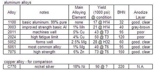
Figure 3 – Strength and hardness comparison of available aluminum alloys.
While nickel sliver is stronger than aluminum alloy 7075, the density of 7075 is only about 1/3 as much. So for equal strength parts, aluminum alloy will be lighter.
In making reels, I use 6061 for most of the frame because it is available in many shapes and sizes. For screws and for the reel foot, I use 7075.
Plating vs Anodizing
An electrochemical plating cell contains an anode (positive electrode) and a cathode (negative electrode). Both are immersed in an electrolyte solution made by dissolving a metal salt. Suppose that the salt is zinc chloride so that the solution has positively charged zinc and negatively charged chloride ions. The item to be plated is the cathode. Here, zinc ions receive electrons from the power supply and become zinc atoms attached to whatever metal is being plated. At the anode, chloride ions give up electrons so that chlorine gas bubbles are formed. The plating solution itself is the major portion of the apparent resistance to current flow. The electric field within the solution has a complex pattern, being stronger at corners of the cathode and at portions of the cathode near the anode. So zinc ions are deposited nonunifomly and the plating is thicker in some areas. The anode should ideally be designed to be of uniform distance from all areas of the cathode so that plating thickness variation is minimized. One way to make the electric field strength at the cathode more uniform is to widely separate the anode and cathode. This means a large size vessel for the cell and a large volume of plating solution.
In an anodizing cell, the aluminum part is the anode. Here, aluminum at the surface of the anode combines with water to form aluminum oxide, hydrogen ions (positive), and electrons that travel toward the power supply. At the cathode, hydrogen ions combine with electrons from the supply so that hydrogen gas bubbles off. Sulfuric acid makes the electrolyte highly conductive, and the major component of cell resistance is in the oxide film being formed on the anode. All points within the solution are at the potential of the cathode and the electric field at the surface of the anode is uniform. The film grows uniformly over the entire anode, regardless of how far portions of it are from the cathode. Electrode design is much simpler for an anodizing cell than it is for a plating cell.
In order to minimize the volume of acid to eventually be disposed, I have used the smallest possible vessels for anodizing cells. They are just large enough to contain the anode and a cathode of comparable surface area.
Safety note: Keep baking soda on hand to neutralize old acid and to clean up acid spills. A one pound box of baking soda is enough to neutralize 32 ounces of 16% acid solution, according to calculations based on my (possibly flawed) memory of high school chemistry. The reaction forms sodium sulfate (a salt) and water. It is a vigorous reaction; add baking soda slowly.
Structure of a Small Anodizing Cell
Several DIY sites consider the anodization of relatively large objects, so you will read about one gallon (and 5 gallon) buckets of acid solution spanned by bus bars. Following is my design for a small anodizing cell. This works for my reel parts and should be more than adequate for any rod parts.
Vessel: Use a wide mouth jar, 16 to 32 ounce capacity, of a plastic that is compatible with dilute sulfuric acid. Good choices are polypropylene (Nalgene) and HPDE. Glass is not recommended because of the potential for fracture and acid spill.
Screw-on Lid: Buy the lid that fits the jar, and use it when storing your acid solution between anodizing sessions. Do not store electrodes in the acid solution; they dissolve with time and ruin the acid by formation of aluminum sulfate.
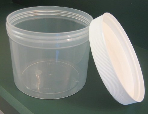
Figure 4 – A polypropylene jar is the vessel for a small anodizing cell.
Anodizing Cover: This is a lid (without threads) that rests on the jar during anodization. It has a rabbet around the edge to pilot on the jar opening. Electrodes are mounted to the cover. Suitable materrials are polypropylene and HDPE.
Cathode: My cathode is a plate of 6061 aluminum sheet. It has a total surface area equal to the area of the largest object that I intend to anodize. It may be OK to have a somewhat smaller area but I have not experimented with this factor. The only problem that I have with this cathode is that it acquires a dark deposit during anodizing, perhaps due to the alloying elements in 6061. The deposit wipes off but is still a nuisance. I will make future cathodes from 3003 sheet, which has less alloy metal content.
Anode Rack: In the language of anodizing, the structure that supports the anode (the item being anodized) and conducts current to it is the rack. Racks can be made of aluminum, in which case they become anodized in the process. But they can be re-used if you strip the anodize layer off in a solution of warm sodium hydroxide (lye; household drain cleaner). When accounting for the surface area to be anodized, include the immersed area of any aluminum rack. Racks can also be made of titanium, in which case they do not need to be stripped between uses, and they do not contribute to anode area. Grade 2 titanium (commercially pure) is easily machined. To attach some reel parts to the rack, I use titanium alloy screws that are popular with R/C model car hobbyists and can be purchased on-line. For reel parts that lack screw holes, I have to make titanium or aluminum clamps that grip in hidden areas.
Where screws or clamps touch the part, there is a area that is not anodized. This area is hidden in the final assembly of the reel.
When designing a rack for reel side plates or spool end plates, I orient the plate vertically in order to not trap air bubbles on the underside.

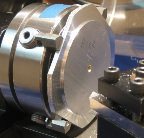
Figure 5 – Polypropylene cover, aluminum cathode, and reel end plate (anode) attached to titanium rack.

Figure 6 – Assembled anodizing cell. Lead wires are color coded.
Electrical Leads: I bolt the cathode and anode rack to my fabricated cover, and make electrical connections at the bolts (stainless steel). Color coding of the leads helps prevent mistakes.
Power Supply: I use a lab DC power supply in current control mode. It might be possible to use a voltage controlled supply, but there is a problem at the start-up of anodization when the load acts briefly like a short circuit.
Thermal Surround: Anodizing generates heat, but we want to keep the process at constant temperature. The disadvantage of a small anodizing cell is that it has a small thermal mass and will heat up quickly. I set the anodizing cell in a bath of cold water and ice, and monitor temperature by brief immersions of the stainless steel probe of an electronic kitchen thermometer. Avoid touching the anode with this probe; it will short out the cell. With the ice bath, I am able to maintain process temperature for loads of up to 1.2 amps. To extend the amp capability of my cell, I am developing a cathode made of 3003 tubing that can be water cooled. This will eliminate the insulating effect of the jar walls from the overall heat transfer situation.

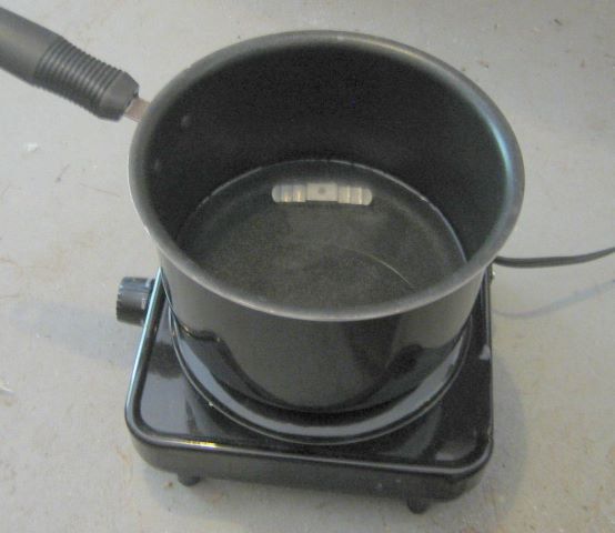
Figure 7 – A current controlled power supply and a thermal bath for temperature regulation.
Structure of the Anodize Layer
Aluminum naturally combines with oxygen to form a covering film of aluminum oxide. This film develops within a day on bare aluminum, and is 2 to 3 nm thick. (I will give thicknesses in nanometers, although you will frequently see the archaic unit Angstrom in the literature. An Angstrom is 10e-10 meter; 10 Angstrom = 1 nm.) Because the oxide occupies 1.5 times the volume of the aluminum consumed, the film is under compressive stress and completely covers the base metal. It also self-heals.
The natural film is very thin and can easily be abraded away, so it provides little protection from corrosion. Although aluminum oxide is an insulator, bare (actually naturally oxided) metal seems to be a conductor when tested with the continuity function of an ordinary multimeter. Electrons can readily traverse the thin coating.
The covering typically obtained in sulfuric acid anodizing is 10 thousand times thicker, about 0.025 mm, or 0.001 inch. By the multimeter continuity test, it is clearly an insulating coat. It is of uniform thickness because it is grown from the inside out, in response to an electrical stress that is uniform. For a 0.001 inch total anodize layer, about 1/3 is outside the initial metal boundary and the other 2/3 is inside. Anodized parts have a small dimensional change from bare parts, about 0.0003 inch on all surfaces. While aluminum oxide does have crystalline phases, the anodize layer is amorphous.
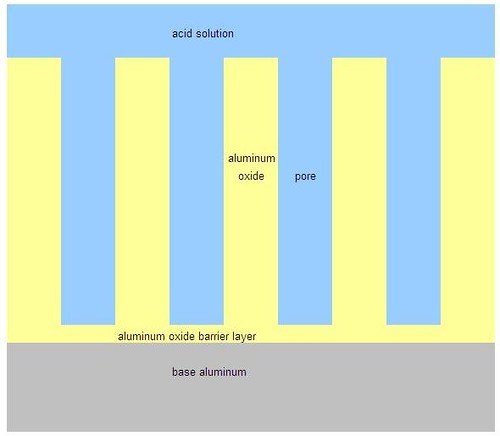
But if the process causes the anode to be covered with an effective insulating layer, how can it serve as an electrode? How can oxygen reach the aluminum to combine? The answer to these questions is in the structure of the anodize layer. The portion of the oxide layer immediately adjacent to the base aluminum is a barrier layer which is more or less uniform material but has various flaws and temporary openings (created by acid dissolution) that allow acid to reach the metal underneath. The thickness of this layer is 10 to 15 nm, or about 1.0 nm per volt of cell potential. The voltage drop in the cell is almost entirely across this barrier. The potential of the bulk of the acid solution is that of the cathode. This explains why the coating is uniformly thick; there is no concentration of electric field at corners. The rest of the coating (outside the barrier) is porous, with the pores oriented normal to the metal surface. The pores are created and maintained by acid dissolution. There are about 800 pores in a square area of 1 micrometer on a side, and these pores are about 15 nm diameter. Overall, the anodize layer resembles a honeycomb.

Figure 8 – Schematic structure of the porous anodize layer.
To better visualize the anodic layer, consider it to be magnified by a factor of 100,000. The magnified layer is 100 inches thick, or a little more than ceiling height. The magnified barrier is 1/16 inch thick, and the magnified pores are 1/16 inch diameter. A square inch of the magnified coating has 50 pores.
The sulfuric acid solution is continually destroying the oxide layer as it is being formed, but the conditions (acid concentration, current density, and temperature) favor growth of the layer. The destruction takes the form of initiating and maintaining the pores, which allow acid to reach the aluminum, and that allows oxide layer growth.
The barrier layer is formed in the first few seconds of cell operation. If the operating voltage is changed during the process, the thickness of the barrier soon changes to maintain 1.0 nm per volt. At the very start of the process, before the barrier is formed, the cell has very low resistance and appears to the power supply to be a short circuit.
Anodize layer growth depends somewhat on the alloy. For some alloys, like 7075, the layer growth will stall if temperature is allowed to become too high. See the reference article for further details.
Conditions for the Sulfuric Acid Process
The standard conditions for sulfuric acid anodizing are:
1. The electrolyte is a mixture of sulfiric acid and distilled water that is 15 to 20% acid by volume. Battery acid from an auto parts store is 35% acid by volume. Mix equal amounts of acid and distilled water to make the electrolyte. Note that when mixing, always add acid to water and not the other way around. Acid concentrations that are either higher or lower impede film growth.
2. A current density of 12 amps/square foot is applied for 1 hour. A total coating thickness of about 0.001 inch is then produced. You may be tempted to reduce heating by using a lower current for a longer time, but this upsets the balance of acid dissolution and oxide formation. The voltage needed to support this current density is in the range of 12 to 18 volts, and is dependent on alloy, temperature, and time.
3. The acid solution temperature is maintained at about 68 degrees F (20 degrees C). Some alloys will fail to anodize properly at higher temperature. For a given current density, increasing temperature reduces the cell voltage. Temperatures significantly lower than 68 F may cause the anodize layer to be cloudy and dark instead of clear.
For more on the anodizing conditions, see the reference article.
Sealing and Dyeing
The porous structure of the anodize layer is ideal for holding dye particles, so an anodize layer can easily be dyed. Many substances can enter the pores and create unsightly stains, so whether dyed or not, the anodize layer should be sealed.
Fabric dye will color anodize layers, but light fastness may be a problem. I have purchased dyes from Caswell (www.caswellplating.com) that are intended for anodize dyeing. I had immediate success with the black dye, but need more trials with lighter colors before they will be satisfactory. Caswell instructs that the dye solution be held at 140 F, so I used a 16 ounce crockpot as a dye vessel. It was shallow enough that I had to suspend reel side plates horizontally so that they would be covered in dye solution. This trapped an air bubble under one side plate, resulting in an undyed area. As in the anodizing cell, it is better to suspend parts vertically.

Figure 9 – This end plate was supported horizontally in the dye bath, and trapped an air bubble.
Dyeing should be done immediately after anodizing since moisture in the air is enough to start the sealing process.
Sealing the anodize layer is a matter of boiling the part in distilled water. This hydrates the porous aluminum hydroxide, causing it to expand and close the pores. More information on sealing is in my reference article.
Another method of producing a bronze to black finish is known as “electrolytic coloring”. This is used commercially on a large scale, but I have not yet found DIY information.
Speculation on Making Rod Parts
Here I will go out on thin ice and discuss rod parts. This discussion is not based on any practical experience. The motivation for using aluminum is lighter weight and the option of dyeing.
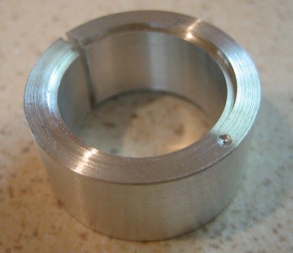
Reel seat caps and rings, or even entire locking reel seats, could be machined of aluminum bar stock. I would use 7075 alloy for strength. The challenge is to design a clamp (as part of the rack) that grips on an unseen interior surface. A spring clamp might be adequate, and grade 2 titanium is available as sheet stock to make thin springs.
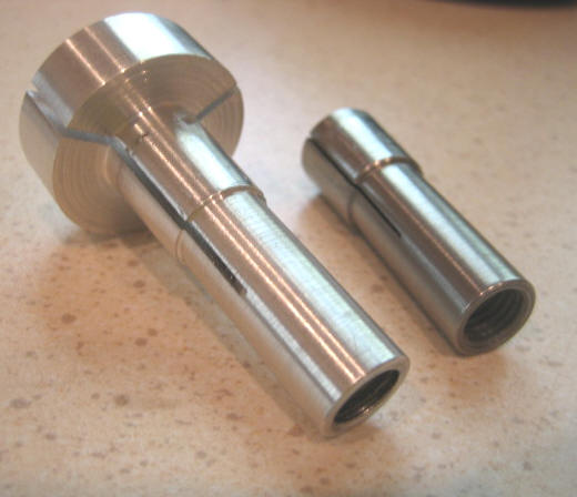
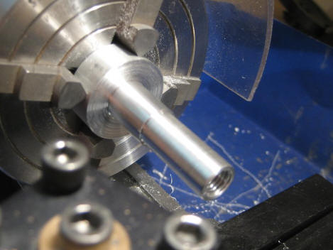
Ferrules might also be made of 7075. Rodmakers sometimes go to the trouble of hollowing their bamboo sections, and aluminum ferrules seem to me to be an equal opportunity for weight reduction. The close fitting cylindrical surfaces of the male and female parts of the ferrule cannot be anodized because of 0.0003 inch growth during the process. These areas could be initially machined oversize/undersize and then re-machined after anodizing to entirely remove the anodize layer and obtain a proper fit. The areas to be re-machined are the obvious locations for rack clamps.
Reference Article: “Technical Data on Anodizing”, northbranchreels.com, 3 March 2012.
Update 18 Aug 2020: I now believe that titanium should not be used for the rack (the anode support). It is better to have an aluminum rack, although it will have to be stripped of the oxide layer each time it is used, which is done with a lye solution. Titanium causes a dark deposit on the cathode, and recently has spoiled several work pieces (anodes) for me. Best to have only aluminum in the acid solution.