Bronze Frame Reel – Rear End Plate

The rear end plate has many details.

I have been making this from C544 bronze rod, but c360 brass flat bar could also be used.

For the 3 weight reel, the ratchet gear is too small diameter to allow a raised thrust pad, as on the 5 weight. So the extra material for spindle threads is on the outside of the plate.

For my most recent reels, I have taken liberty with the lightening hole pattern in order to make room for engraving.

The earlier blog posts cited for the Front End Ring are also relevant for this part.

Posted in End Plate, Plans | Leave a comment

Bronze Frame Reel – Front End Ring

The North Branch Reels metal shop is not yet back in operation after its relocation from Michigan to New Mexico. I have unpacked almost all the moving boxes and built two new workbenches.

Here you see the mill on one bench, waiting to be lifted onto its chip pan. The elephant in the room is a large woodworking project that is occupying the second bench (foreground). The metal shop will wait until this is finished.

So I have had little new blog material for some time. This seems to be a good time to go through the drawings for my current reel design, which I will refer to as the “Bronze Frame Reel”. Over the past two years I have made many posts about these reels. It may be called “Reel 44” in some places.

The drawings to come describe two reel sizes, which I designate as “5 weight” and “3 weight”. They originally appeared in this blog on 29 May 2014 and 14 July 2014.

I have not gotten around to making an overall assembly drawing, but the design is simple and there are many photos in this blog.

Here are the two sizes of front end ring. I have been making them from c544 bronze, which is available only as round bar stock. You can buy 2.5 inch diameter from On Line Metals. For 3 inch diameter, go to a specialist metal supplier like Farmers Copper.

Handling and sawing the large diameter rod stock is difficult; you might consider making the part from brass flat bar.


Dates of earlier blog posts on making this part:
17 May 2015, 24 Feb 2015, 11 Dec 2014, 30 Sept 2014, 12 July 2012, 12 Nov 2011
Use the “Archives” pull-down box on the right side of this screen to quickly locate past articles.

Posted in Plans, Ring | 4 Comments

The K’Nex Furling Machine

I have fished furled leaders for several years now. At first I made them by twisting with an electric drill:

Furled Leader


Later, I made a hand cranked furling fixture: https://northbranchreels.com/2014/07/31/furling-machine/

A week or so ago I was contacted by Ben, a resident of my adopted town of Rio Rancho. He wanted to make leaders but was not prepared to make a machine like mine. So he improvised with the kid’s building set K’Nex. Here are 3 pictures of his furling head.


I am not familiar with K’Nex, but it looks as if the input gear here may be several inches diameter. Three high speed furling shafts run 14.2 times as fast as the input crank. (My speed-up ratio is 84/17 = 4.9 .) He also has a fourth spindle with ratio 5.9 .

His setup frame has adjustable post locations, so he is making not only leaders but Tenkara lines of up to 15 foot length.

As on my machine, he has a dead weight to maintain the line tension while furling. I think that this is an important feature.

How could you make a furling machine if you had no K’Nex nor any capability to make gears? I just did a search for “plastic gear” and came up with a promising supplier, http://www.gizmoszone.com/shopping/agora.cgi?page=plastic_gear.htm . The category “spur gear” seems to be all 0.3 module, which is a tiny tooth. But from “compound gear” you can find 0.5 module with up to 60 teeth. The high speed gears are listed as “motor gear”. Use some caution here; a gear with fewer than 12 teeth (at 20 degree pressure angle) will have an undercut tooth profile. Undercut can be avoided by using “addendum modification”, which is what I suppose Gizmo’s Zone has done. When a modified pinion is meshed with a standard gear, the pressure angle is more than 20 degrees (which is no problem, even though we may have used a 20 degree cutter) and the center distance is more than standard (which is also no problem, if you are able to calculate or fudge the correct center distance).

Posted in Line/Knots | Leave a comment

Jemez River Reels?

I haven’t written any blog posts for some time now. It is because I have been busy packing and moving to New Mexico. The motivation is better weather.

So reelmaking operations now have to fit into the 0.5 car space left in a 2.5 car garage. I will keep the name “North Branch Reels”, as there is still visitor activity on this web site.

Posted in Uncategorized | 4 Comments

A Foot Fixture for the Lathe


Since starting this hobby in 2010, I have built about 50 reels. For every one of these, I shaped the top of the reel foot with a vertical mill using this rotary table fixture. This is a labor intensive process requiring many milling passes, all in the axial direction. When I am done milling, there is hand work to sand out the facets produced by 5 degree indexing of the rotary table.
I have done all this for each reel in order to make the top surface of the foot cylindrical rather than conical. The AFFTA reel foot standard does not specify the shape. I like the cylinder better; if the top radius is 0.35 inch at the tip, it is 0.35 all the way up. With a cone, the top radius will expand to 0.46 inch as you move toward the center. When the reel seat is a screw lock type, it doesn’t make much difference. But for the simple and elegant cap-and-ring seat, the cylindrical surface ensures that the ring contacts the center of the foot rather than the two sides. The ring then deflects into an ellipse and becomes a more compliant spring, so the grip of the seat on the foot is better.

A lot of time could be saved if the top of the foot were cut with a lathe instead of with a mill. After several years of subconcious thought, the form of a lathe fixture has revealed itself to me. This form starts with a rectangular block of aluminum, milled to remove much of the waste material.

At the headstock end of the fixture there are two centers, angled 7.5 degrees apart.

At the tailstock end there is a single center. It is collinear with one of the two headstock centers. To make it work (temporarily) with the other headstock center, I have used a special center drill that makes an 82 degree cone instead of the standard 60 degree.

I now turn an 0.688 inch diameter using the off-angle center. This is the mounting surface for the foot. On my small Sherline lathe, I had to make this cut in segments.

Then I can rework the 82 degree cone to the standard 60 degrees.

Here I am using a dial indicator and a split ring of .040 inch radial thickness to verify the location of the end of the foot on the fixture. This dimension (0.480 inch on the drawing below) is critical, as it determines the top radius of the foot for a given tip thickness. This “calibration” procedure caused me to adjust the foot end to .460 inch.

The mounting point is a drilled and tapped hole. A clearance hole will not do because a nut on the under side would interfere with the lathe bit.

The last step is to turn a 0.625 inch diameter on the collinear centers so that no part of the fixture will be in the path of the lathe bit.

Fixture in use.

Posted in Fixtures, Foot, Turning | Leave a comment

Wire Bending

Here is the latest variation on my reel click design.

I have used this basic pattern for a long time. The spring is a round wire and the pawl has a groove that acts as a cam against it. Click strength is not adjustable after the reel is assembled. (Not really true, you can always adjust the wire bends.)
For small trout reels, there is perhaps no need to bias the click for higher strength in the outgoing direction, but I have been doing it anyway. At first, I was making the pawl asymmetric. Later, I made the pawl symmetric but made one spring pin larger diameter than the other. In this third variation, the pawl is symmetric and the two pins are the same diameter, but the spring has asymmetry. Changing a reel from right hand to left hand wind is now just a matter of reversing the spring.

Here is the final form of the spring. It is “stainless music wire, spring temper”. The bends at the ends snap into grooves on the spring posts. The reverse bend makes the click asymmetric.

To produce springs the are consistent, I needed a fixture for making the bends.

This is the fixture, an aluminum block fitted with several steel pins. It also has some scribed lines that serve as guides.

The first bend is an angle of 98 degrees. I want it to have a .094 inch inner radius, but am bending around a .125 inch diameter pin because there will be spring-back.

Not shown in this photo is a second aluminum block that helps me push on the wire; it shows in the next two photos.

Bend 2 is the reverse kink that makes the spring asymmetric.

And here is the final bend, again around a pin somewhat smaller that the desired inner radius.

Posted in Forming, Spring | Leave a comment

Engraved Reels

My engraver is now operational; here are the first reels. This is the same bronze frame design I have made for more than 2 years, but with some porting holes left out to make room for lettering.

This is the culmination of a project that I started in July 2015, when I bought an Acme thread tap so I could make my own anti-backlash leadscrew nuts. Most of my blog posts since last July are on the design and fabrication of the engraver.

Update 22 June 2016: The engraving example here was done with a square end mill of .018 diameter. Being a “standard” length end mill, the cutting length is 3x the diameter, or .054 inch. These are carbide end mills, and are quite brittle. I broke several. So then I switched to “stub” length, or .027 inch cutting length, but these still break. Most recently I have bought T2 style tools from 2L (2Linc.com). I think that this is a much stronger configuration. I bought .015 tip diameter and 45 degree included cone angle, so when I make the groove .005 inch deep, the width at the top of the groove is .019 inch.

Posted in Engraving/Marking, My Reels | Leave a comment

Collet Grip

I have one more problem to solve before my CNC engraver is operational. It is that end mills come loose in the spindle.

This is the spindle, it is 1.2 inch diameter and uses a “WW” collet (0.125 inch bore). WW collets were originally designed for watchmaker’s lathes. When an end mill comes loose, it can migrate either up or down from the desired height.

To make sure that I was getting the collet tight, I drilled two holes in the brass knob at the top, and made a “pin wrench” to fit.

I can hold the other ridged surface with soft jaw pliers.

From hex stock, I made a test part to fit the chuck. With a small end wrench, I can feel the grip of the collet.

I am sorry to find that the grip is not very good. I do not think that I have a bad collet, as I bought another and the result is the same. It is not a problem of grease in the wrong place; I washed the collet and brass hex piece in denatured alcohol.

This reminds me that I had a solid carbide end mill (3/8 inch diameter shank) once slip in an R8 collet.

I have a lot of 3/8 end mills, so I also bought a 3/8 inch “end mill holder”. It has a set screw and so is suitable for HSS and cobalt steel end mills that have a flat. It does not help to hold a carbide end mill that has no flat.

If anyone knows how to improve collet grip, I would be interested to hear.

Update 10 April 2016: I am adding a photo here to illustrate engraving gone bad.

Here I have used a .018 inch diameter square end mill and have aimed for a .005 inch groove depth. The decorative pattern was done first and all was satisfactory to that point. The lettering followed, and that is where the collet grip on the end mill failed. The letters went on clockwise; you can see that N on MICHIGAN looks OK, but after that the groove becomes deeper. By the time it got to the N on NORTH, the groove was nearly .06 deep. I am amazed that a .018 end mill would survive. The material is c544 bronze, a free machining alloy.

I am thinking that a WW collet is the wrong thing for this application. I have set my brass test piece (1/8 shank and 1/4 hex) in my Dremel tool collet and found that it has a better grip than the WW. Then I put it in the ER16 collet chuck of my lathe and the grip was great; I am sure there would be no slip. So the next thing is to harangue the spindle maker to offer an ER8 chuck.

I have sought help from the forum at practicalmachininst.com, and have received many responses. Two that may have the quickest benefit: reduce friction a) at the conical interface of the collet and spindle, and b) at the interface of the spindle and the draw tube knob. Here is the photo that one responder requested:

The area at the top of the (aluminum) spindle is 0.8 inch OD and 0.5 inch ID. Maybe a Teflon washer there would help.

Update 11 April 2016: Yesterday I made a Delrin AF washer to go between the pull tube knob and the spindle. By my test with the brass part and the small end wrench, this was a big improvement in collet clamping. Then I put a little grease on the conical surface of the collet, and I believe that there was further improvement. So I will try running this way for a while and see if there are any further problems.

Update 15 April 2016: With the engraving end mill better clamped, I feel that I can now get a satisfactory engraving.

This is a test part with some machining mistakes on the profile and porting.

Posted in Engraving/Marking, Milling | 10 Comments

Bushing/Clicker Wheel

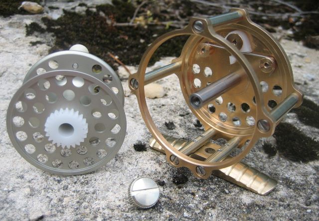
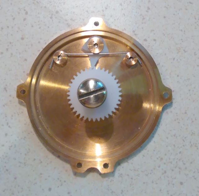
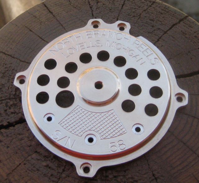
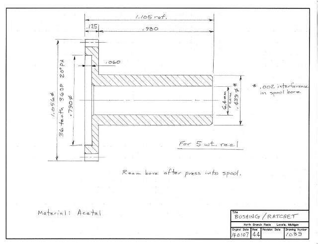
For several months I have been building an engraving mill and not producing any reels. So now I am back on reels, and have to re-familiarize myself with the processes. At the center of the reel is a critical part made of Delrin. It is the bushing for the spool, and it is one piece with the wheel of the clicker.

I have been calling the toothed part a “ratchet”, but that may not be correct. Dictionaries say that a ratchet allows just one direction of rotation. A clicker has to allow bidirectional rotation, but the drag may be biased.
Although the teeth are cut with an “involute gear cutter” it is not really a gear either, since it does not mesh with anything.

I managed to scrap 3 parts before producing a useable bushing/clicker wheel. So here is a photo record to help me the next time I do this part.

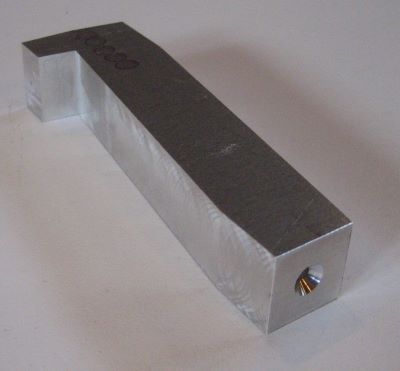
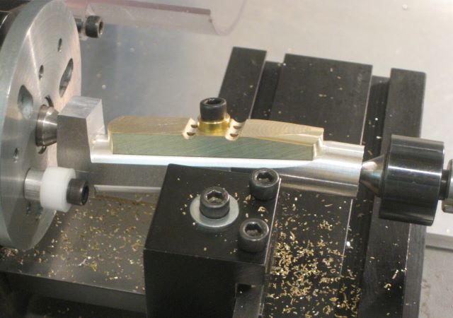
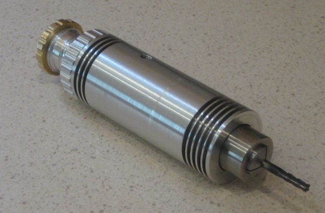
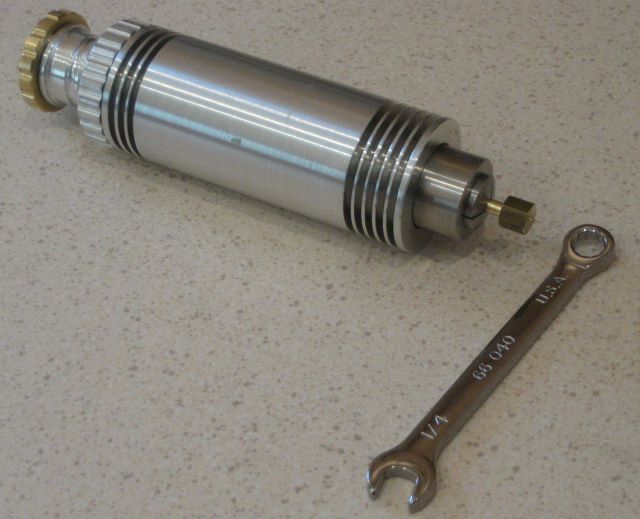
This is the simple fixture that I use, just a piece of shaft material drilled and tapped at one end, plus a clamp screw, washer, and spacer.

First I make a cylindrical blank that is .015 or .020 inch longer than the finished part.

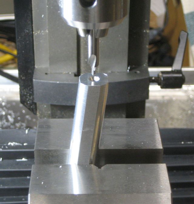
The fixed spindle for the reel is .250 inch diameter. I drill the blank with a .250 diameter drill.

When a brittle material like metal is drilled, the hole is likely to be a little larger than the drill bit. But when drilling a tough material like Delrin, the hole is little smaller than the drill bit.

So when I push the fixturing shaft into the new hole, it is a firm fit.

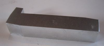
I next turn a .900 inch diameter (a little smaller than the gear dedendum circle) for a length of .97 inch, just .01 inch shorter than the shank of the finished part.

So far, concentricity of diameters has not been critical.

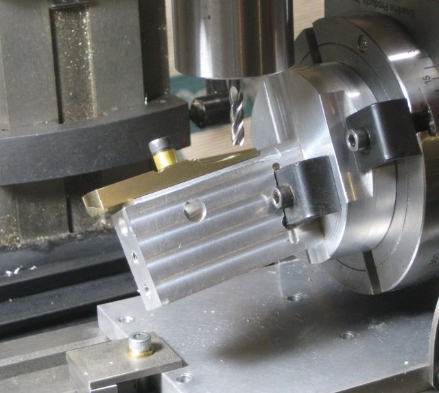
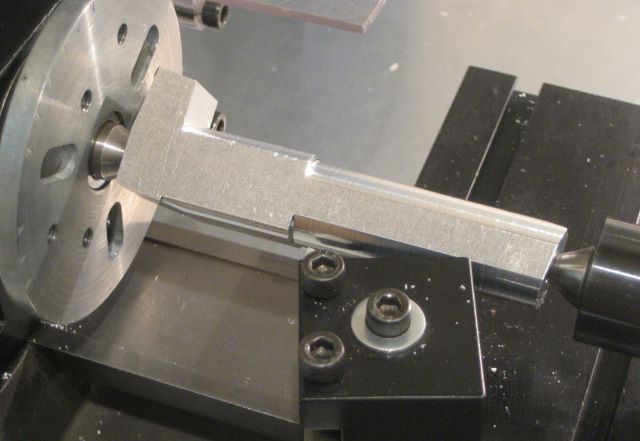
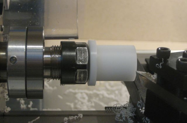
But the gear OD has to be concentric with the bore. So I re-do the press of the part on the fixture, letting the shaft protrude from the toothed end.

Then I center the fixturing shaft in a 4 jaw chuck.

The gear OD can then be turned concentric with the shaft.

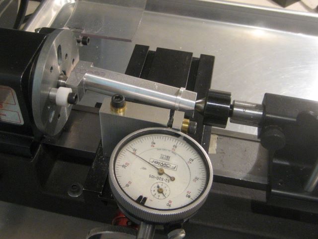
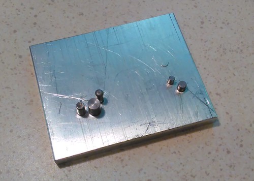
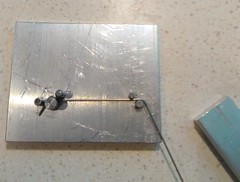
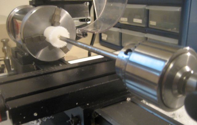
My 4 jaw chuck will mount to the mill’s rotary table, but the adapter may not bring it to center. So I check runout on the rotary table, and adjust the chuck as needed.

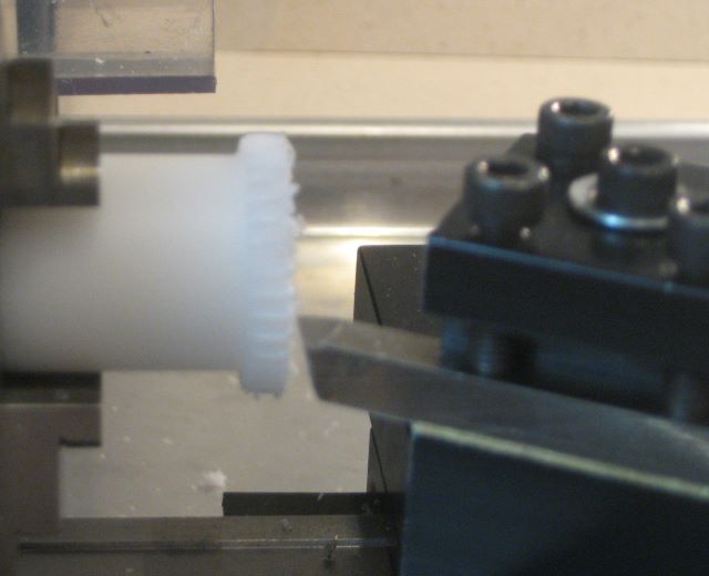
The teeth can then be cut.

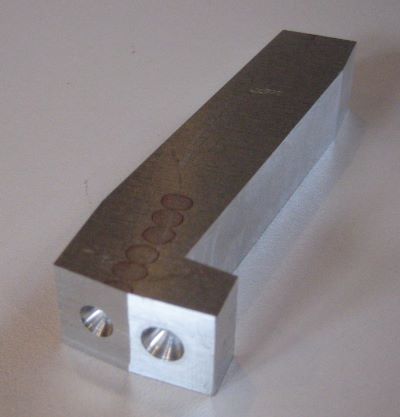
The finished gear teeth are “fuzzy”, due to the toughness of the material.

I can then remove the fixture and ream the bore.

This reamer is 6.4 mm diameter, or .252 inch. Like a drilled hole, the reamed hole is a little smaller than the tool. It is a good running fit to a .250 diameter spindle.

At the toothed end, I then trim the part to final length.

This removes some of the “fuzz” from the gear teeth.

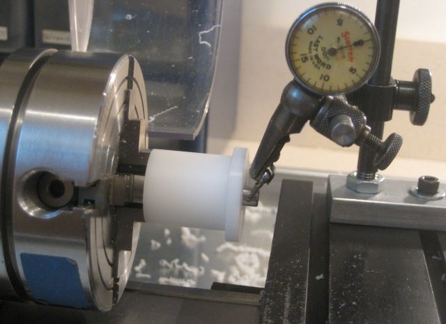
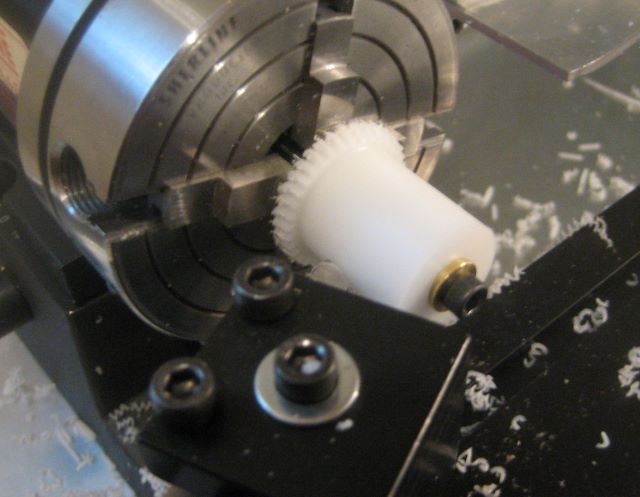
In preparation for turning the shank diameter, I again center the mandrel (the fixturing shaft) in a 4 jaw chuck.

Since reaming, the part slips easily over this mandrel.

At this point, I measure the bore of the mating spool.

My spool drawing calls for a .4375 inch reamed bore, but the truth is that my Sherline lathe does not have enough low speed torque to make this. So I have to use a boring tool, somewhat less accurate. Also, the spool is anodized, which reduces its bore.

I turn the shank of the part so it has .001 to .002 inch interference with the spool bore.

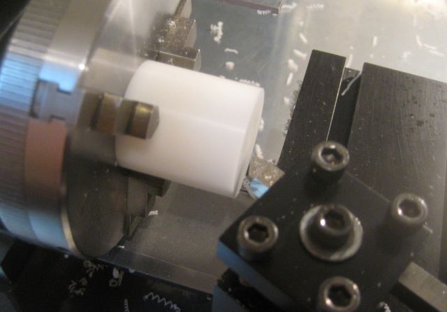
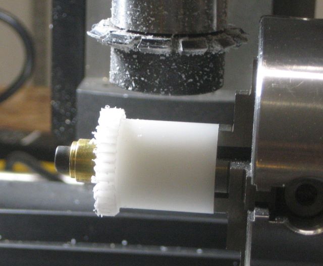
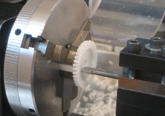
Here I am facing the other side of the gear teeth, removing the last .01 inch extra width.

The recess can then be cut.

This particular boring tool works well on Delrin when moved radially with the cross slide.

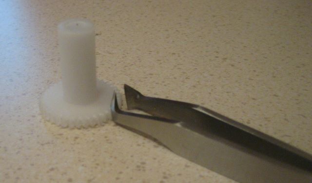
Finally, I give the gear teeth a haircut. This nipper is a “desprue” tool from Micromark.

Posted in Bushing, Ratchet/Gear, Thrust Bearing | Leave a comment

More of Greg’s Reels

Greg is an Ohio based bamboo rod maker. In November 2014 I posted pictures of two reels that he made from my plan set (eclecticangler.com).

Greg is now seriously into reel production, using CNC to assist on the more complicated parts.

He has a CNC converted Precision Matthews mill and uses Fusion 360 to make the solid models from which G code can be generated.

One of the reels in these pictures has an aluminum frame; it is meant to go with a lightweight graphite rod.

Note to myself: The deburring wheels that Greg likes are “3M Scotch-Brite EXL”.

Posted in CNC, Reels by Readers | 6 Comments