
Since starting this hobby in 2010, I have built about 50 reels. For every one of these, I shaped the top of the reel foot with a vertical mill using this rotary table fixture. This is a labor intensive process requiring many milling passes, all in the axial direction. When I am done milling, there is hand work to sand out the facets produced by 5 degree indexing of the rotary table.
I have done all this for each reel in order to make the top surface of the foot cylindrical rather than conical. The AFFTA reel foot standard does not specify the shape. I like the cylinder better; if the top radius is 0.35 inch at the tip, it is 0.35 all the way up. With a cone, the top radius will expand to 0.46 inch as you move toward the center. When the reel seat is a screw lock type, it doesn’t make much difference. But for the simple and elegant cap-and-ring seat, the cylindrical surface ensures that the ring contacts the center of the foot rather than the two sides. The ring then deflects into an ellipse and becomes a more compliant spring, so the grip of the seat on the foot is better.
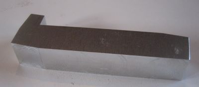
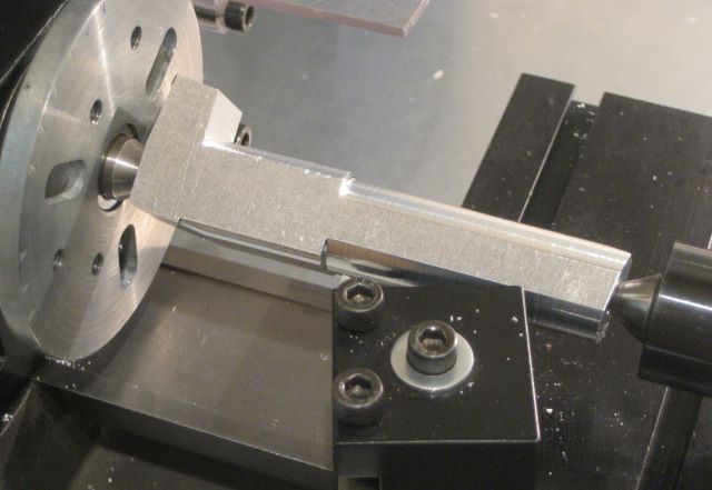
A lot of time could be saved if the top of the foot were cut with a lathe instead of with a mill. After several years of subconcious thought, the form of a lathe fixture has revealed itself to me. This form starts with a rectangular block of aluminum, milled to remove much of the waste material.
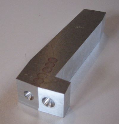
At the headstock end of the fixture there are two centers, angled 7.5 degrees apart.
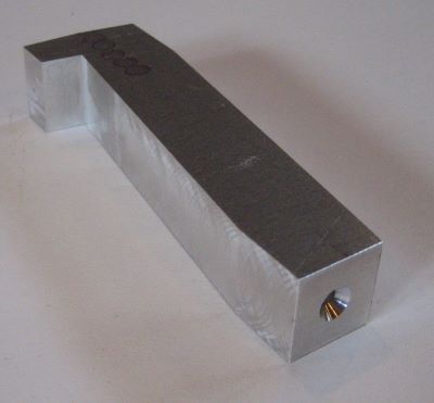
At the tailstock end there is a single center. It is collinear with one of the two headstock centers. To make it work (temporarily) with the other headstock center, I have used a special center drill that makes an 82 degree cone instead of the standard 60 degree.
I now turn an 0.688 inch diameter using the off-angle center. This is the mounting surface for the foot. On my small Sherline lathe, I had to make this cut in segments.
Then I can rework the 82 degree cone to the standard 60 degrees.
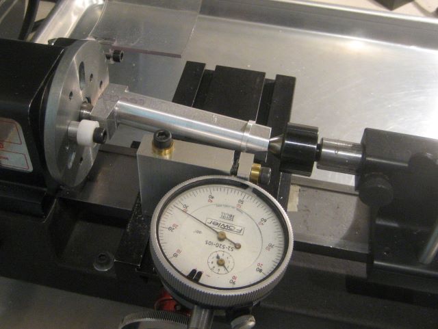
Here I am using a dial indicator and a split ring of .040 inch radial thickness to verify the location of the end of the foot on the fixture. This dimension (0.480 inch on the drawing below) is critical, as it determines the top radius of the foot for a given tip thickness. This “calibration” procedure caused me to adjust the foot end to .460 inch.

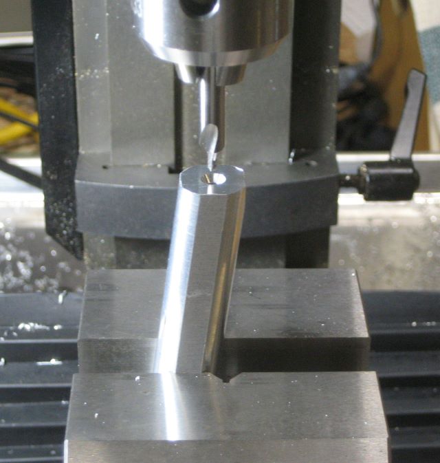
The mounting point is a drilled and tapped hole. A clearance hole will not do because a nut on the under side would interfere with the lathe bit.

The last step is to turn a 0.625 inch diameter on the collinear centers so that no part of the fixture will be in the path of the lathe bit.
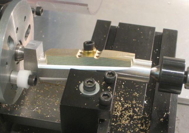
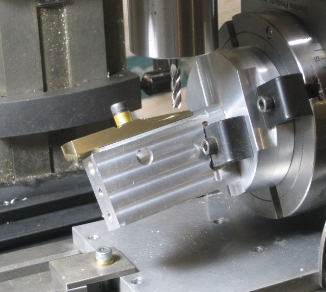
Fixture in use.


-
Recent Posts
Categories
Archives
Links
Meta
-
Join 105 other subscribers
