Reel 37 Pawl

The acetal pawl is slightly asymmetric so that line payout is at higher resistance than retrieval.

In earlier reel designs I put a spacing washer between the pawl and backplate, but this little washer was difficult to make. Here the spacer is integral to the pawl.

Posted in Pawl, Plans | Leave a comment

Reel 37 Bushing, Knob

The bushing is pressed into the spool, and rides on a .2500 inch diameter spindle. For a good running fit, I finish the bushing bore with a “standard” 6.4 mm (0.252 inch) reamer. This is a close enough fit that it is necessary to ream a second time after press into the spool.

The ratchet is integral with the bushing and is cut with a standard involute gear cutter.

The knob as drawn has a cylindrical outer surface, but the one in the photo has been shaped.

Posted in Bushing, Knob, Plans, Ratchet/Gear | Leave a comment

Reel 37 Spindle

I have been making spindles from stainless shaft material, which is pre-ground to an accurate diameter and smooth finish.

The screw that secures the spool is of c792 nickel silver (12% Ni) which is an excellent free machining material.

Posted in Plans, Spindle | Leave a comment

Reel 37 Spool

On fixed spindle reels like this, the knob and its counterweight attach directly to one face of the spool. So I have made the face flange thick enough to accept 4-40 screw threads.

A step-by-step pictorial on making this part was posted here 1 June 2013, “One Piece Spool”. I used the mill to remove most of the material from between the flanges.

The porting hole pattern is documented on a separate drawing, which also considers the frame.

I make the port holes by plunging with a 3 flute end mill.

Posted in Plans, Spool | Leave a comment

Reel 37 Foot

The foot is entirely made on the mill, except that I use the lathe to turn a sanding mandrel for the bottom surface.

For the many posts on machining the foot, go over to “Categories” at the right edge of the page and click on “Foot”. Particularly see 10 Sept 2013, “New Foot Fixtures”.

Posted in Foot, Plans | Leave a comment

Reel 37 Frame

This is a difficult part; there are many operations and a correspondingly high possibility of making an error that will force a start-over.

A step-by-step pictorial is in an earlier post of 10 June 2013, “One Piece Frame”.


All the critical dimensions requiring concentricity are cut with one chucking on the “grip”, the smaller diameter extension of the material blank that you see in the photo. The “grip” is axially long enough that the outer diameter surface of the part clears the jaws of my chuck.

Posted in Frame, Plans | Leave a comment

Reel 37 Plans

I have not made a post recently but I have been busy making reels. To keep the blog going, I will make a series of posts showing the several detail drawings.

Lacking a name for this design, I will just call it “Reel 37” since 37 is the sequence number of the first reel of this design.


It is a simple click reel, with the pawl biased to provide higher resistance for outgoing line.

This is the assembly drawing; detail drawings will follow in subsequent posts.

The design covers six sizes of reel, sized to accommodate weight forward floating lines of sizes 0 through 5. Here is a raw material list for the largest size.

Reel sizing was established in a post of 10 May 2013, “Line Volume”.

Posted in My Reels, Plans | 8 Comments

Shaping the Knob

The knobs on my reels have just been simple cylinders. They might look better with some shaping, perhaps a “waist”.

Here is a material blank mounted on a mandrel, ready for turning.

I want to make a concave arc cut on the cylinder, and the setup is to use the mill as a lathe.

The mill headstock is horizontal and a tall toolpost is fastened to the rotary table. I have used a similar setup to cut convex spherical surfaces on counterweights and center screws.

This plan view sketch may help to explain.

Here is the shaped cylinder.

New knobs on reels under construction:

Posted in Knob, Turning | Leave a comment

Pawl Modification

This is the pawl shape that I have used for some time now.

I like it because the active part of the spring is just a straight wire (easy fabrication). This wire bears on the pawl at the top edge of a groove milled across the pawl.

A pawl can be quickly profiled if it is mounted on a post at the center of a rotary table.

Recently I made a change in the groove where the spring wire is in contact. Formerly (top sketch) I cut the groove straight across, then made two more cuts on an angle at each end of the groove. These are located asymmetrically so that there is more resistance when line is paying out. Now I am cutting it on a large radius (bottom sketch), slightly off the centerline of the pawl.

With the new groove, I am able to provide the same pawl tip tangential force (T) at a larger moment arm (d) on the pawl, resulting in a smaller contact force (F) on the spring. This has reduced the spring stress to 64% of what it was with the straight groove.

On the pawl with a straight groove, the contact point of the spring is always at the apex of the end angle. The moment impressed on the pawl by the spring is nearly proportional to the angle of pawl rotation. With the arcing groove, the pawl “rolls” on the spring and moment arm (d) increases as the pawl rotates, making the moment proportional to the square of the pawl rotation angle.

Cutting the arcing groove requires a new fixture so that the pawl can be held off-center on the rotary table.

Posted in Click, Pawl | 3 Comments

A Riveting Experience

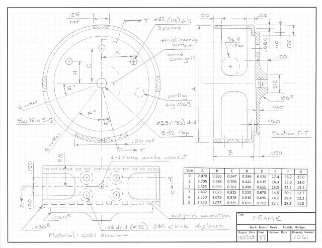
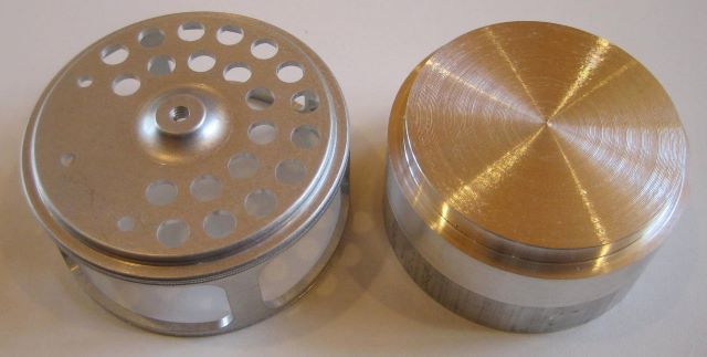
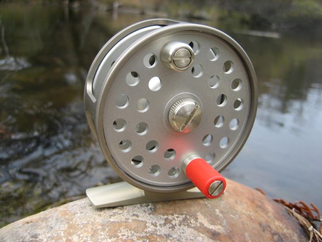
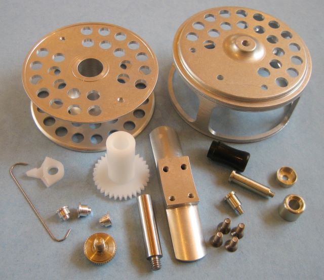
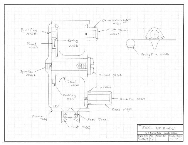
The click mechanism for my reels mounts to the reel backplate by three posts; two are spring pins and the third is a pivot for the pawl. For some time now, I have fastened these by custom made screws. For a neat appearance, I have recessed the screw heads into counterbores. More recently my reel backplates are too thin to accommodate the counterbore, so I have installed the posts by press fit. But sizing the pin of the fit is tedious, and not always successful. I decided to try riveting, which is a typical process for commercial reels.

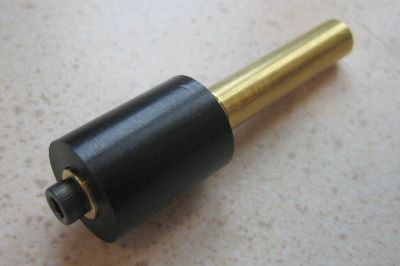
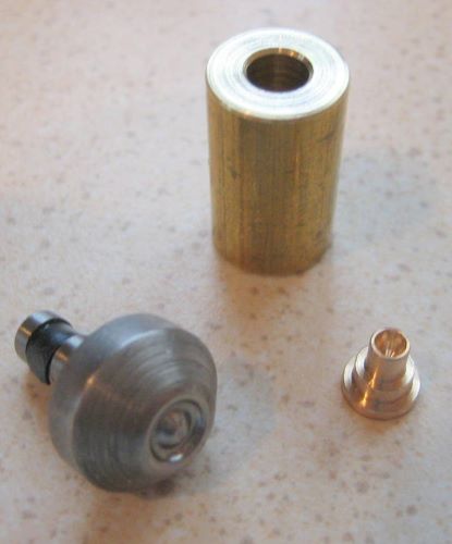
Here is a pressing anvil for a 1/8 inch tubular rivet (AN450), a homemade rivet, and a brass sleeve for the anvil. The sleeve lets me use my arbor press rather than purchase the special squeezer tool.

For the rivet I chose c544 phosphor bronze as a compromise of machinability and formability.

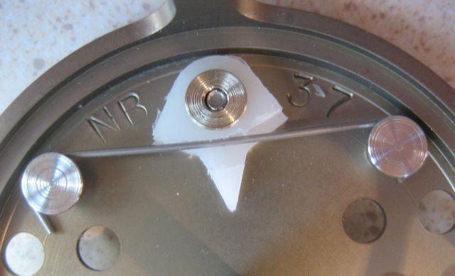
And here is the rivet installed on a scrap of aluminum. The forming is neat, no split.

One problem is a slight anvil impression on the aluminum. It may be that the arbor press allows me to apply excess force, so I need some practice.
Later: Indeed, a little care while squeezing avoids any marks on the substrate.

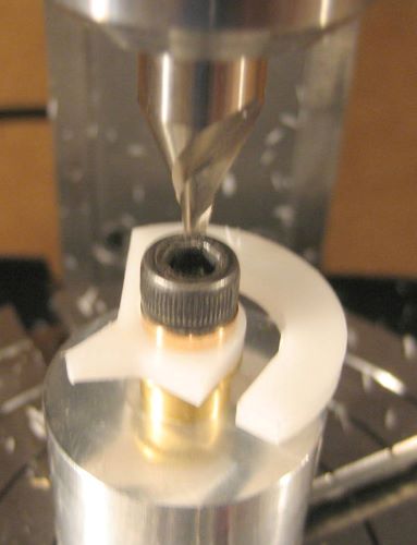
21 Dec 2013: Considering electrochemistry, what rivet material is suitable for an aluminum substrate? High strength alloy 7075 splits when formed. 6061 is just marginal, on the edge of splitting. The solution seems to be grade 2 titanium.

Note: Tub Rivet Die SM200-4504

Posted in Click, Forming | Leave a comment