
I have not made a post recently but I have been busy making reels. To keep the blog going, I will make a series of posts showing the several detail drawings.

Lacking a name for this design, I will just call it “Reel 37” since 37 is the sequence number of the first reel of this design.

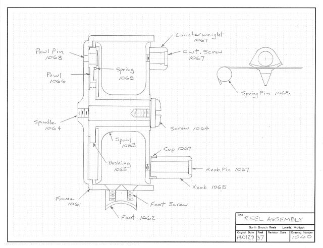
It is a simple click reel, with the pawl biased to provide higher resistance for outgoing line.
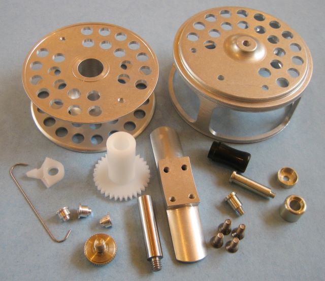
This is the assembly drawing; detail drawings will follow in subsequent posts.
The design covers six sizes of reel, sized to accommodate weight forward floating lines of sizes 0 through 5. Here is a raw material list for the largest size.

Reel sizing was established in a post of 10 May 2013, “Line Volume”.

Wow. Just amazing, what a piece of art. I know I should leave a comment before… but every time I come here I get a bit overhelmed… I need to get the time to check all your posts thorougly some day. I understand how much devoted work are involved in creating and building these kind of incredible things. Thanks for sharing.
Nice Stuff. I have been building my own reels and making line for years now. I do not use a machine shop to make them though, just a hacksaw, drill, and files and some sandpaper. Perhaps you have seen reelsmithing.com, I am Michael’s mentor. Anyway I just finished building a lower for an AR15 and I ma surprised how similar they are when it comes to a chunk of machined Al, some pins, screws and springs…so simple.
Peter,
Thank you.
I do recognize your name from reelsmithing.com
Michael sells some of my reel plans on eclecticangler.com
Dave
I’m building a #4 size to your plans, and am really enjoying myself. It’s a rather different scale of work for me, and has been a good winter project to shake down the shop after moving last year. Just wanted to say thanks, and I’ll send you some pictures when I’m done.
Chuck,
Let me know if I can help with anything. Gear cutter needed, etc.
I ended up making screw attach posts for the pawl. The pawl needs some “final fitting” with file, reamer, c’sink etc, and it is handy to be able to remount it several times.
Dave
Hello Dave – missing some dimensions on the foot, or misunderstanding how you get there. 2.5″ long, 5.25 wide, by how high? IE, I can place the A/2 cut for the frame at any height from the foot. Trying to model the parts in CAD so’s I understand them, and there’s not enough info on this one.
Chuck,
On drawing 1062, look at the end view in the lower right hand corner. The dimension 0.31 locates the low point of the A/2 arc from the bottom of the foot.
Keep me up to date on your progress.
Dave
Ah ha, got it now. Progress is good now that the Bridgeport is operational. Minor mishap on the frame, debating on a re-do. Thanks a lot!