
This is the pawl shape that I have used for some time now.
I like it because the active part of the spring is just a straight wire (easy fabrication). This wire bears on the pawl at the top edge of a groove milled across the pawl.
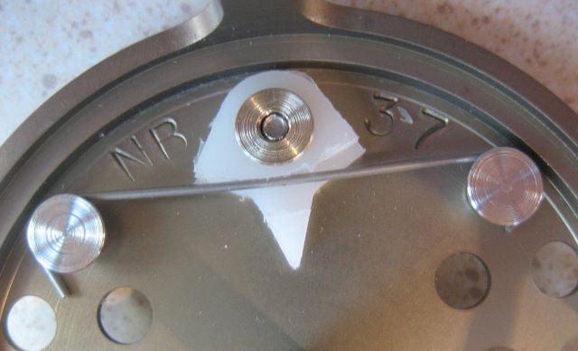
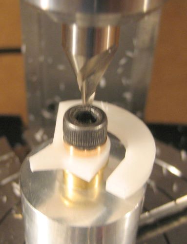
A pawl can be quickly profiled if it is mounted on a post at the center of a rotary table.
Recently I made a change in the groove where the spring wire is in contact. Formerly (top sketch) I cut the groove straight across, then made two more cuts on an angle at each end of the groove. These are located asymmetrically so that there is more resistance when line is paying out. Now I am cutting it on a large radius (bottom sketch), slightly off the centerline of the pawl.

With the new groove, I am able to provide the same pawl tip tangential force (T) at a larger moment arm (d) on the pawl, resulting in a smaller contact force (F) on the spring. This has reduced the spring stress to 64% of what it was with the straight groove.
On the pawl with a straight groove, the contact point of the spring is always at the apex of the end angle. The moment impressed on the pawl by the spring is nearly proportional to the angle of pawl rotation. With the arcing groove, the pawl “rolls” on the spring and moment arm (d) increases as the pawl rotates, making the moment proportional to the square of the pawl rotation angle.
Cutting the arcing groove requires a new fixture so that the pawl can be held off-center on the rotary table.


great thinking, Dave
Hi, I’m not that good a running a mill so, do you make these paws for sale?
Leroy…
Hi Leroy,
We have not communicated for a while, but I think that I still have your Email address. I will answer there. If you do not here from me, try using the address on the “Contact” page of my blog.
Dave