
When I first started anodizing (this blog, 4 May 2010) I followed instructions from DIY web sites, and felt that I had satisfactory results. Recently I borrowed a technical reference book set that covers anodizing, dyeing, and sealing. It is a two volume set, “The Surface Treatment and Finishing of Aluminum and its Alloys” by Wernick, Pinner, and Sheasby. The edition that I borrowed is the fifth (1987) but the current edition is the sixth (2001). In what follows, I will refer to the book set as “Wernick”. Reading Wernick has caused me to change my methods, namely to return to the standard current density of 12 amps/square foot and to pay closer attention to temperature regulation.
This two volume set is expensive because of the limited audience. Here I will review what I think are the key points for the home hobbyist. Several plots below use data that I extracted from Wernick. Other material is from my own experience.
Anodizing Conditions
For sulfuric acid anodizing, which is the practical process for the DIYer, the conditions to maintain are
1. acid concentration of 15 to 20% by volume,
2. current density of 12 amps/square foot applied for 1 hour, and
3. acid solution temperature of about 68 degrees F (20 degrees C).
What I learned from Wernick is the reason for each of the conditions. Knowing why helps keep one from going astray. Before discussing the reasons for these conditions, I first have to describe the anodize coating.
Natural Oxide Film
Aluminum naturally combines with oxygen to form a covering film of aluminum oxide (Al2O3). This film develops within a day on bare aluminum, and is 2 to 3 nm thick. (I will give thicknesses in nanometers, although you will frequently see the unit Angstrom in the literature. An Angstrom is 10e-10 meter; 10 Angstrom = 1 nm.) Because the oxide occupies 1.5 times the volume of the aluminum consumed, the film is under compressive stress and completely covers the base metal. It also self-heals.
The natural film is very thin, and so provides little protection from corrosion. Although aluminum oxide is an insulator, bare (actually naturally oxided) metal seems to be a conductor when tested with the continuity function of an ordinary multimeter. Electrons can readily traverse the thin coating.
Anodized Coating
The covering typically obtained in sulfuric acid anodizing is much thicker, about 0.025 mm, or 0.001 inch. This covering is grown in an anodizing cell under the conditions stated above. By the multimeter continuity test, it is clearly an insulating coat.
In electroplating, metal ions in solution are deposited on the cathode (-) of the plating cell and gas bubbles may form on the anode (+). For example, zinc plating can be done with a zinc chloride solution. Zinc will plate out on the cathode and chlorine gas will bubble from the anode (!). The zinc will plate most heavily where the electric field is the strongest, at corners.
In a sulfuric acid anodizing cell the aluminum to be covered is the anode, and hydrogen gas will bubble from the cathode. The coating will be of uniform thickness because it is “grown” from the inside outwards. For a 0.001 inch total anodize layer, about 1/3 is outside the initial metal boundary and the other 2/3 is inside. While aluminum oxide does have crystalline phases, the anodize layer is amorphous.
But if the process causes the anode to be covered with an effective insulating layer, how can it serve as an electrode? How can oxygen reach the aluminum to combine? The answer to these questions is in the structure of the anodize layer. The portion of the oxide layer immediately adjacent to the base aluminum is a barrier layer which is more or less uniform material but has various flaws and temporary openings (created by acid dissolution) that allow acid to reach the metal underneath. The thickness of this layer is 10 to 15 nm, or about 1.0 nm per volt of cell potential. The voltage drop in the cell is almost entirely across this barrier. The potential of the bulk of the acid solution is that of the cathode. This explains why the coating is uniformly thick; there is no concentration of electric field at corners. The rest of the coating (outside the barrier) is porous, with the pores oriented normal to the metal surface. The pores are created and maintained by acid dissolution. There are about 800 pores in a square area of 1 micrometer on a side, and these pores are about 15 nm diameter.
To visualize the anodic layer, consider it to be magnified by a factor of 100,000. The magnified layer is 100 inches thick, or a little more than ceiling height. The magnified barrier is 1/16 inch thick, and the magnified pores are 1/16 inch diameter. A square inch of the magnified coating has 50 pores.
The sulfuric acid solution is continually destroying the oxide layer as it is being formed, but the conditions (acid concentration, current density, and temperature) favor growth of the layer. The destruction takes the form of initiating and maintaining the pores, which allow acid to reach the aluminum, and that allows oxide layer growth.
The barrier layer is formed in the first few seconds of cell operation. If the operating voltage is changed during the process, the thickness of the barrier soon changes to maintain 1.0 nm per volt. At the very start of the process, before the barrier is formed, the cell has very low resistance. I use a power supply that has an electronic current limit, and if it is powered up into a short then the current limit circuit latches into a zero current, zero voltage state that can only be exited by power cycling. My procedure to get started is to preset the current limit using a dummy resistor, then turn the voltage control knob to zero. An instant after dunking the electrode assembly into the acid solution, I ramp the voltage up to and past the point where the current limit takes over.
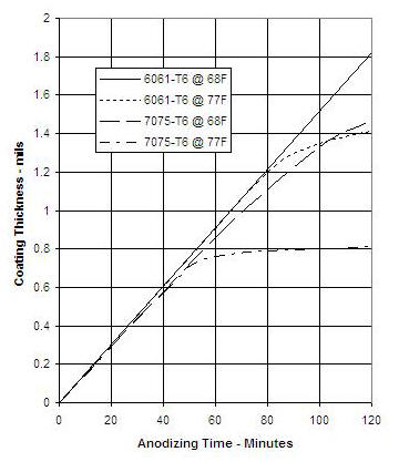
Anodize layer growth depends somewhat on the alloy. The plot below shows the growth in two common alloys, for two different temperatures. For alloy 7075, a small increase in temperature increases the rate of acid dissolution enough to stall out growth at 0.0008 inch.
Acid Concentration
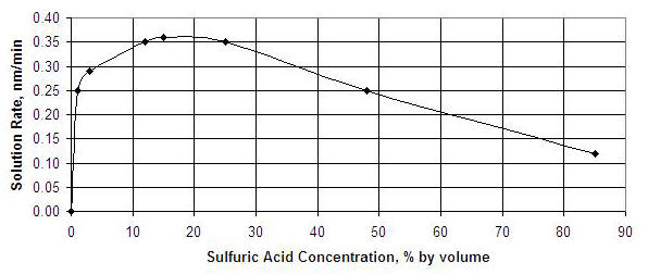
What is special about 15 to 20% concentration (by volume) of the acid? Wouldn’t it be possible to increase the concentration and also increase the current density and get a faster growth of the anodize layer? The answer is no. Surprisingly, the effectiveness of the acid will decrease at higher concentration. The figure below shows dissolution rate of the oxide layer as a function of acid concentration. A concentration rate of 15 to 20 % produces the greatest dissolution. I assume that concentrations outside this peak range run the risk of not maintaining open pores.
A note on acid concentration: The battery acid sold at auto parts stores is sulfuric acid with a concentration of 30 to 35% by volume. If you dilute with an equal volume of distilled water, you get the desired concentration.
Current Density
The first plot shows anodize layer growth rate for a current density of 12 amps/square foot. At half this density, I still get an insulating coating but I cannot say how thick. A better policy is to use the current density for which growth rate is known.
Temperature
When the acid is colder than room temperature, the anodize coating on 6061-T6 can have a dark appearance (this blog, 6 Mar 2011). The first plot above shows that too high temperature can stall layer growth. My policy now is to try to maintain 66 to 70 degrees F.
Cell Voltage
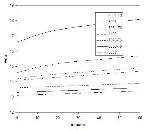
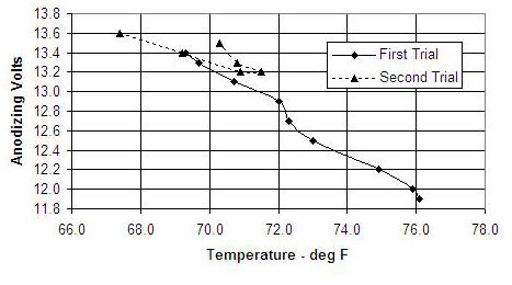
Running at 12 amps per square foot requires 12 to 15 volts from the power supply. The exact voltage depends on the specific aluminum alloy in the process, and on the degree to which the layer is already formed. The plot below is an illustration of what to expect, but the voltage value will vary somewhat with the cell design.
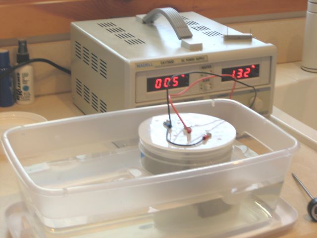
I think that the best policy is to use a lab type power supply with an adjustable current limit and run under constant current control rather than constant voltage. An advantage of this strategy is that the resulting cell voltage is a sensitive indicator of acid solution temperature. Below is some data that I took while anodizing spool ends. In the first trial, I started with acid that was warmer than I wanted (approx. 67 F). I cooled the cell by placing it in a cold water bath, and the voltage gradually increased. At the start of the second run the acid was below 68 F. It warmed during the process (decreasing the voltage) until the water bath was able to cool it again.
When I did anodization at 6 amps/square foot, the cell voltage was about 7. This is evidence that the barrier layer acts as a linear resistor.
Temperature Control
Uncontrolled, the cell temperature is likely to rise during the process. This is because electric power is being injected and because formation of aluminum oxide is an exothermic process. My anodizing cells are plastic jars of about one quart capacity. I place them in a cold water bath (usually with a few ice cubes) to absorb the excess heat. For a 12 square inch anode that needs 1 amp current, the bath has to be at about 50 deg F to maintain constant acid temperature.
Lab Safety
Keep baking soda on hand to deal with a possible acid spill. To neutralize a quart of acid of 16% concentration you need a pound of baking soda.
While glass is impervious to acid, it is not a good vessel for an anodizing cell because of the possibility of breakage. Acid compatible plastics are polypropylene (Nalgene) and HDPE. Yes, milk bottles are made of HDPE, but they are blown with such thin walls that leaks are a threat.
When combining battery acid with distilled water, always add acid (to water): AAA.
The cell cathode will produce hydrogen gas, but only a small quantity at low current like 1.0 amp. Still, avoid open flames in the immediate area of the cell. Also, keep your nose away from the cell as it is not good to breathe hydrogen gas.
Use a small anodizing cell so that acid disposal problems are minimized. For doing reel parts, I can get away with a 1 quart container. The container needs to be tall enough that reel end plates can be oriented vertically so that bubbles are not trapped against the underside.
Recently I found that McMaster-Carr has a 1200 ml polypropylene jar that is the same diameter as the 1000 ml (33.8 oz) jars that I have been using. This extra height makes the electrolyte level in the jar less critical.
Cathodes
I made my first cathodes from 6061 aluminum. I find that they accumulate a dark deposit (alloy metal?) that I must wipe off after each 1 hour process. This is a nuisance, so I will make the next cathodes from 1100 or 3003, which have less alloying component.
Jigs
The structure that supports the anode and provides a current path is called a jig. The jig can be made of the same aluminum that is being anodized, and becomes anodized itself. So the surface area of the jig, or at least its submersed part, should be included when calculating the required current. To re-use a jig, strip off the anodize layer with a lye solution (drain cleaner). When stripped this way, 6061 aluminum retains a natural finish but 7075 turns black. This is evidently due to the difference in alloying metals.
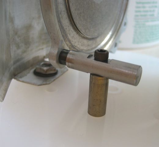
A jig can also be made from titanium. You will hear tales of how difficult it is to machine titanium, but such stories are about high strength/hardness titanium alloys. Grade 2 titanium is “commercially pure” and not difficult to machine. I have made several jigs of Grade 2 rod. Below is the jig for a reel end plate. The end plate is fastened to the jig using a titanium alloy cap screw. Titanium does not develop an insulating coating and can be re-used without stripping. When doing spool plates, I have a jig that clamps on a feature on the back of the plate, and this feature is hidden in the final assembly of the reel. The point of contact between jig and workpiece of course receives no anodize layer, and should be carefully chosen.
The idea that titanium can be part of the anode assembly, even though it does not develop an insulation layer, seems to me a puzzle. Why doesn’t it short out the whole cell when it is in contact with the acid? There is then a direct path through the acid from anode to cathode that has no barrier layer (apparently), and the barrier is the only source of resistance to current flow. The answer given by Wernick is that titanium is “protected by anodic passivation”. Not being an electrochemist, this statement has no meaning for me, but I suspect that it has to do with the relative positions of aluminum and titanium on the electrochemical scale. Read the definition of of “passivation” in this Electrochemistry Dictionary. It discusses the development of protective films and mentions that current becomes zero in “anodic passivation”. I have conducted an experiment that convinces me that no current passes from the titanium to the acid, at least when aluminum is also part of the anode.
It is my policy to not let any metals into the acid solution other than aluminum and titanium and their alloys. This is to prevent contamination of the acid. Even these metals should not be left in the acid when there is no current, as they will dissolve.
Dyeing
Anodizing creates a transparent and porous film, and the pores are an excellent place to store dye molecules. So far I have not dyed, and so have nothing further to report. There are mentions at the DIY sites that RIT dye is not UV resistant, so I plan to purchase the on-purpose anodizing dyes from Caswell.
Sealing
Since the pores in the film are a sponge for stains, they need to be closed. This is done by chemical hydration of the aluminum oxide. As I understand the process, some of the aluminum oxide will combine with water to form aluminum oxide hydroxide, AlO(OH). A naturally occuring form of aluminum oxide hydroxide is the mineral Boehmite, a component of bauxite. Wernick calls the hydrated oxide in anodize film “pseudo-Boehmite”.
Aluminum oxide hydroxide is more voluminumous than aluminum oxide, so the hydrated material swells, closing the pores. Not all the oxide film is hydrated; Wernick gives the following composition for the film before and after hydration.
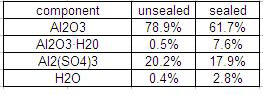
I do not understand why this table lists the hydrate as Al2O3·H2O rather than as AlO(OH).
The oxide-hydroxide is somewhat softer and more pliable than the original oxide, but this seems to me to not be a disadvantage. Aluminum oxide is extremely hard and brittle; it is used to make sandpaper.
The procedure for hydration is to boil the anodized parts in distilled water for half an hour. It is important to use distilled water because the minerals that are typically in tap water will inhibit pore closing.
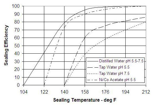
In my first anodizing efforts, I used a “sealant” sold by Caswell (nickel acetate). This now appears to me to be unnecessary, at least for undyed parts. For dyed parts, the sealant may combine with dye molecules to form an additional pore closing agent. Another aspect of the sealant is that it reduces the need for pure water in the sealing process. The chart below depicts a “sealing efficiency” quantity that is determined by dye staining trials on a sealed surface.
In an industrial process, it might be difficult to maintain a vat of water at the required purity. But for DIY work there is plenty of distilled water at the grocery store.
Update 9 March 2012: I have been anodizing end plates, which are large enough to need 1.45 amp current. To keep the acid solution down to 72 deg F, I have to make liberal use of ice cubes in the water bath.
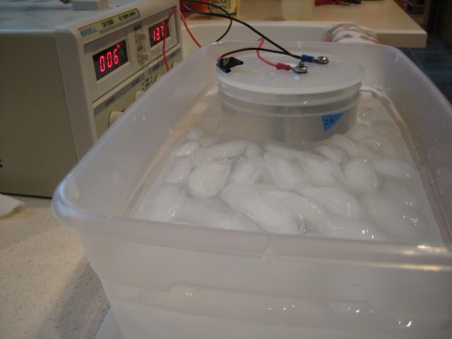
The water bath measures about 35 deg F. I figure that the heat generation in the cell is 20 watts (1.45a * 14v) electric plus 5 watts (140 BTU/ft^2/mil) exothermic heat of formation, or a total of 25 watts. The polypropylene wall of the cell is 0.062 inch thick, and the area of contact with the water bath is a cylindrical surface 4.5 inches diameter and 2.5 inches high. Taking the thermal conductivity of polypropylene to be 0.12 W/(m * deg C), the wall thermal resistance is about 1.0 (deg F)/W. The overall thermal resistance is evidently (37 deg F)/(25 watts) = 1.5 (deg F)/W, so convection coefficients in the water bath and in the acid solution have some effect. So 1.5 amps is the limit for anodizing in this cell, unless I take further measures to promote heat transfer.
Here is the jig that I made to anodize two reel feet.
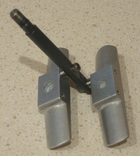
It is made from titanium rod. The reel feet are 7075 aluminum, which is more sensitive to high temperature than is 6061 (see first graph of this post). The two feet need only 0.70 amp, so temperature control is not a problem.
Update 29 Nov 2012: Finally got some feedback on anodize coating thickness. I made two special samples 0f 6061 aluminum that I processed at 12 amp/sq. ft., acid s.g. = 1.15, and temperature 68 deg F. One sample ran for 30 minutes and the other for 60 minutes. Acoording to the charts above, the coating thickness should be 0.5 and 1.0 mil. I sent the two samples to an anodizer who has a meter for film thickness measurement, and the result was 0.34 and 0.56 mil.
While this is less than I expected, I do not plan to change my process. I think that 0.56 mil is an adequate film thickness.
Update 18 Aug 2020: I now believe that titanium should not be used for the rack (the anode support). It is better to have an aluminum rack, although it will have to be stripped of the oxide layer each time it is used, which is done with a lye solution. Titanium causes a dark deposit on the cathode, and recently has spoiled several work pieces (anodes) for me. Best to have only aluminum in the acid solution.

Hi Dave, i was having a couple issues with my anodizing and found, by trial and error that temp control in the anodizing bath was the one issue, and connectivity which was solved by the use of titanium rod for connections. I have been following the guide lines that Ron Neuman suggests and have had good results so far.
Leroy……….
Leroy,
I think that we are on the same page here. It was Ron Newman’s instructions that got me started. Also useful is the Caswell plating manual. But I was pleased to find the Wernick book that shows “why” and not just “how”.
Dave
Pingback: Anodizing Temperature Control | North Branch Reels