Rear End Plate

I have made prototypes of two sizes of my “Fixed Spindle Reel” (see post immediately preceding this one), and am now starting the first reel for a customer. Also, I have committed to deliver a plan set by the end of October. This plan set will include step-by-step instructions for the more complex parts.
The Rear End Plate is the most complex part of the reel. As I am making one this week, I am taking pictures that illustrate the step-by-step instructions.
Many of these steps are repeated for the Front End Ring.

Step 4: Rounding corners on the bar stock. This allows turning on the lathe.

This 4 jaw chuck is a good milling vise, but only if it is restrained from angular motion (see bolt, washer, and brass spacer).

Step 5: Flatten the top. I do not have/use a fly cutter.

Step 6: Find X and Y positions by reading the engraved scales on the mill, in addition to the handwheels. These scales lack pointers, so my pointer is a brass square pushed against a way cover support. It works on the Y axis also.

Step 6: A notebook. Short term memory deteriorates as we age. I write all calculated arbor positions in a notebook. This reduces mistakes.

Step 6: Rough mill the recesses.

Step 7: Drill and ream the center hole. The chuck goes straight from mill to lathe with no re-chucking.

Step 8: Bore inside surfaces to final dimension.

Step 8: Turn inside flat surfaces to final dimension.

Step 9, 10, 11: Turn the part over and re-center. The center hole is the only feature available for alignment. The indicator is running on a brass part that closely fits the hole.

Because the chuck jaw step is higher than the flange thickness of the finished part, I have inserted a .040 thick spacer between the jaws and the part. This spacer is just a round piece of aluminum sheet. Cutting sheet metal is a problem. I cut an oversize circle with a scroll saw, then hold it in a chuck to drill 3 holes, then bolt it to a faceplate to turn the outer diameter.
In re-chucking, you must not only re-center but also get the part down flat on the chuck jaws. Here you see a skin cut at the four corners. I can measure thickness at all corners to see if it is flat (i.e., parallel to the other side).

Step 12: Rough mill the outside profile.

Step 14: Rounding the corner. Here I have turned outside surfaces to final dimension and am making a round corner. The procedure is to cut some chamfers and then smooth with a file.

On Sherline’s lathe you can cut a taper/chamfer by rotating the headstock.

Step 15: Re-check the center of the rotary table before drilling the bolt circle.

Step 15: Drill and counterbore the bolt circle. Angular position here is very critical. Remember that the rotary table has backlash, and take it out just as you would for the X and Y axes. The rotary table also has a locking setscrew; I had my table for some time before I found it.

Step 16: Plunge mill the inner radii on each side of the lugs. Again, Angular posiiton is critical. I plunge a 1/4 inch roughing end mill before finishing with this 3/8 standard end mill.

Step 18: Fasten to toolplate. We cannot finish while in the chuck; jaws stand in the way. This toolplate has a pin on the back that pilots into the rotary table.

Step 19: Cut the main outer radius. I start with a roughing end mill and finish the last .010 inch with a standard end mill.

Steps 20, 21: Round the lug corners. Some minor adjustments of radius are needed to make this .175 convex arc meet the .188 concave arcs on a common tangent. I find it easiest to make these adjustments with a 2 flute end mill.

Step 23: Wet sand part face. It could be held in a 4 jaw chuck for this, but here I am using the faceplate that was needed to turn the front end ring inner diameter.

Step 24: Drill, counterbore, plunge mill.

Posted in End Plate | Leave a comment

Reel for WF3F

Here is a smaller version of my Fixed Spindle Reel.

It is 2.25 ring diameter, 3.7 ounces, and holds WF3F plus 25 yards backing.

Many of the parts are identical to those of the original, larger reel. Just the end plates and spool ends are reduced diameter.

Here it is with the original 5 wt. reel.

I will be making these this winter, but at my usual snail’s rate of production – I still work with non-CNC Sherline lathe and mill. If anyone is interested, they are $400. Contact dave49@wildblue.net .

Posted in My Reels | 1 Comment

Acid Concentration

My reelmaking is quite dependent on the anodizing process. Running this process consistently means controlling three conditions:
1. Current density (12 A/in^2)
2. Temperature (68 deg F)
3. Acid concentration
Recently it occurred to me that my acid mixing is haphazard. My reference book discusses acid concentration in terms of “percent by volume”, and I now realize that I do not know what this means. The problem is that 10 fluid ounces of water mixed with 10 fluid ounces of acid yields a solution that is less that 20 fluid ounces volume. When I mix the water and acid, I first put a measured volume of distilled water in a container, and then add enough automotive battery acid (already an acid-water mixture) to make up twice the volume. I am not sure how much acid this takes.

To monitor acid concentration on an ongoing basis, one needs a hydrometer (any auto parts store).

I bought this one because it shows specific gravity, not just some colored balls floating.

Whatever concentration I arrived at, I am getting satisfactory results (although I still am not capable of measuring film thickness) and I intend to maintain this concentration. My acid solution measured SG = 1.15 . The container of my source battery acid says SG = 1.265 .

A table of sulfuric acid concentration (on a percent by weight basis) vs specific gravity can be found here. Below, I have plotted the data.

So I am using a solution that is about 21% acid by weight.

Posted in Anodizing/Plating, Measuring | 1 Comment

Hardness Test

On 15 Dec 2012, I posted about some aluminum rod stock that was supposed to be 7075, but might be something else because it did not anodize properly. I theorized that it might be 2024 (a known poor anodizer) because the vendor also stocks 2024. How might I easily identify non-conforming material when I have to order more 7075 rod? It is now time to order so the problem becomes urgent.

Last winter I sold several reels and so had some funds to pour back into this consuming hobby. I bought two items, a load cell (Ebay NOS) and a microscope with a measuring reticle. These are good general purpose items, but I also thought that I might be able to do a hardness test with them.

In a Brinell test, you push a hardened ball into a material sample with a known force. The diameter of the indentation is then measured. The Brinell Hardness Number (BHN) is calculated as

BHN = F / (Pi/2 * D * (D – sqrt(D*D – I*I)))

F = Force applied (Kgf)
D = ball diameter (mm)
I = indentation diameter (mm)

A standard Brinell hardness test involves a 10 mm ball and a force of 3000 Kgf. I have a “1 ton” arbor press and a 1/4 inch (6.3 mm) diameter material sample. Clearly, I will have to do a non-standard hardness test. I selected a 4 mm ball and 200 Kgf (440 lbf) because the expected indentations would then be in the 1 to 2 mm range. I made test samples of 6061-T6 (95 BHN, expect 1.60 mm indent), 7075 (150 BHN, expect 1.29 mm indent), and of the mystery material. If it is indeed 2024-T4, then it will be 120 BHN and will have a 1.43 mm indentation.

Here is my load cell, resting on an aluminum disk of the same diameter, and both resting on the arbor press.

I have placed a bronze disk, with a drill point dent, on the crowned button of the load cell. The ball rests on the dent without rolling away. A Delrin spacer retains the disk in position but does not interfere with pressing.

Here I have placed a test sample on the ball, guided by a plastic sleeve.

I had a few false starts in the pressing. It was easy to overshoot when cranking the arbor press up to load. Once I had my technique established, I produced these three indented samples.

The 6061 sample has a 1.75 mm indent (vs 1.60 expected). The 7075 sample has a 1.22 mm indent (vs. 1.27 expected). The mystery material also has a 1.22 mm indent. By this test, it is indistinguishable from the 7075 that anodized properly. So perhaps it is not 2024, but what could it be? When I buy more rods, I guess that I am stuck with anodizing samples of each to check for unsatisfactory material. (Update 12 Sept 2012: Ordered 10 rods at 2 ft. each; all anodized properly.)

Remarks on the test:
I am a 150 lb weakling and 440 lbf is about the largest force that I can achieve with adequate control (i.e., no overshoot) from this “1 ton” arbor press.
Under magnification, the edges of the indents were quite sharp and easy to measure with the reticle.
My microscope has 3 objective lenses for 20X, 40X, and 100X magnification. I used 40X here, and was able to resolve indentation diameter to .025 mm (.001 inch).

I suspect that the greatest weakness in my test procedure is control of the force. Obviously it would be better to have a purpose-built Rockwell tester (a heavy, expensive unitasker). But had the problem material been 2024, I think that my test would have adequately shown the 120 BHN hardness.

Posted in Measuring, Testing | Leave a comment

Downsized Click

My new “Fixed Spindle Reel” is 2.78 inch diameter, but I also intend to make a smaller version of 2.28 inch diameter. The two versions can use mostly the same parts, except that end plates and spool ends must be reduced. Another problem area is the click.

The original click runs on 0.95 inch center distance between ratchet center and pawl pivot. For the smaller reel, I must reduce this to 0.75 inch. The two changes that I made are a) smaller ratchet (27 vs. 30 teeth) and b) shorter pawl. To confirm the new design, I had to make a prototype.

The pawl is not symmetrical, but not to the degree that was possible with the larger click. Two flats, at 30 degree angle to horizontal, set the outgoing and incoming drag levels. If I cut the incoming flat at too small radius, then the mechanism tends to jam when spool direction is reversed from incoming to outgoing.

Update 3 Oct 2012: I put this click into a small version of my Fixed Spindle Reel (see post of today) but it did not function well. In the reel, it tended to jam upon spool direction reversal, regardless of flat dimensions. So I have changed to a 24 tooth ratchet and correspondingly longer pawl. This ends the jam problem.

Posted in Click, Pawl, Ratchet/Gear | Leave a comment

Spindle Wrench Set

The fixed spindle of my new reel design is a piece of stainless shaft material that holds a bronze thrust washer against the reel back plate. It is secured by a custom screw with a large head.

I did not want to put any screw slots or drill holes in the spindle or in the screw, so I needed another way to adequately torque this connection. I made this soft jaw (aluminum) wrench set.

The small wrench is for the spindle, and fits inside the reel frame.

The larger wrench holds the screw.

Together, they lock the spindle in place tightly so that removing the spool retaining screw should not loosen this joint. At final assembly, the connection will get some Loctite.

Posted in Tools | Leave a comment

Fixed Spindle Reel

My earlier designs were “rotating spindle”, which require full front and back end plates and a crank to turn the spool. This new design is “fixed spindle” which means an open front end ring, no crank, and a spool that comes off with just 1 fastener.

The frame is clear anodized aluminum, and the spool end plates are anodized aluminum that has been electrolytically colored, as described in the blog post preceding this one.


The ratchet and pawl are Delrin, borrowed from an earlier design.

The open front end ring, lack of a crank, and lightening holes help to reduce weight. This reel is 4.2 oz. It hold WF5F and 100 yd. backing. It is 2.78 inch diameter.

Posted in My Reels | 5 Comments

Electrolytic Coloring

My anodized aluminum reel parts have mostly been undyed, that is, clear anodize. I did try out some dyes (23 April 2012) and even produced a reel with black end plates (9 May 2012). Other than black, I did not like the dye colors that I got. Leroy’s comment on the dye sample post was that it takes some experimentation to get lighter colors to work right.

But I also found that I would need a larger vat to sucessfully dye, so that parts could be hung vertically to not trap air bubbles. It seems to me a big problem to maintain a larger vat at the required temperature, 140 deg F.

Not long after this effort, Alan showed me his Bougle reel with a nicely colored spool (26 May 2012). He described the color as “champagne”. I found it difficult to capture the color in photographs.

Then I came across a reference to a process for anodized aluminum called “electrolytic coloring”. This article, an advertisement by a supplier to the commercial anodizers, said that their coloring electrolyte could produce bronze colors from “champagne to black”, dependent on process time. Maybe this is what Hardy used on reels like Alan’s. The electrolyte is a proprietary formulation, available in 42 gallon drums. Probably not suitable for a hobbyist like me. I found no information on DIY electrolytic coloring on the web, only that the process is also known as the “two step” process, wherein the first step is a conventional anodize using a DC power source, and this is followed by a second process with coloring electrolyte using AC power.

There is a comprehensive reference book on anodizing which I used as the basis for an earlier post (3 March 2012). When I borrowed the 5th edition through my local library, I did not connect with any information on “electrolytic coloring”. I now think that the info was there, but in a chapter titled “Anodizing in Architecture” that I did not bother to read. So when I recently visited relatives in the Champaign IL area, I made it a point to visit the U of I Engineering Library, where I found the 6th edition of the reference book. And there I found enough info to get me started.

Some points about electrolytic coloring:
1. What is added to the porous anodize layer is not dye molecules but heavy metal ions/atoms. Tin for bronze shades, copper for red, molybdenum for blue, etc.
2. The coloring process immediately follows anodizing, before sealing.
3. The metal atoms travel to the bottom of the pores in the anodize layer and so make a more durable color than dyes, whose molecules stay in the tops of the pores.
4. A long process time with almost any metal ion/atom will produce black. But at this point, the pores have been filled from bottom to top and may be difficult to seal. (Sealing is hydrating the aluminum oxide so it expands and forces the pores shut at the tops.)
5. This process is done at room temperature.
6. An AC power supply is used, low voltage. While the voltage waveform may be sinusoidal, the current waveform is not. Half cycles of current in one direction are larger than the half cycles in the other direction. This provides the necessary “throwing” of metal ions into the anodize layer.
7. When designing an anodizing cell, we don’t have to be concerned with the shape and placement of the cathode. This is because all the resistance of the cell is in the anodize layer, causing the electric field to be uniform over the entire anode. The oxide layer will grow uniformly. Not so with coloring. Significant resistance is in the electrolyte (as in plating) and the electric field will not be uniform unless some attention is given to the design of the counter electrode. Variations in color intensity can occur.
8. The rack (anode support) in an anodizing cell can be titanium, but only aluminum should be used in a coloring cell.

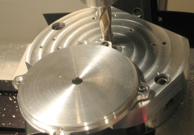
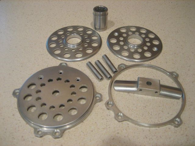
My initial effort is to color the spool ends of a newly designed reel. What appears to be the challenge is “racking”, which is arranging the anode support and electrical connection inside the anodizing cell, and later in the coloring cell. We need to carry over the electrical connection from anodizing to coloring because we are growing an insulating layer on the part. The only place to electrically connect to a spool end is its bore.

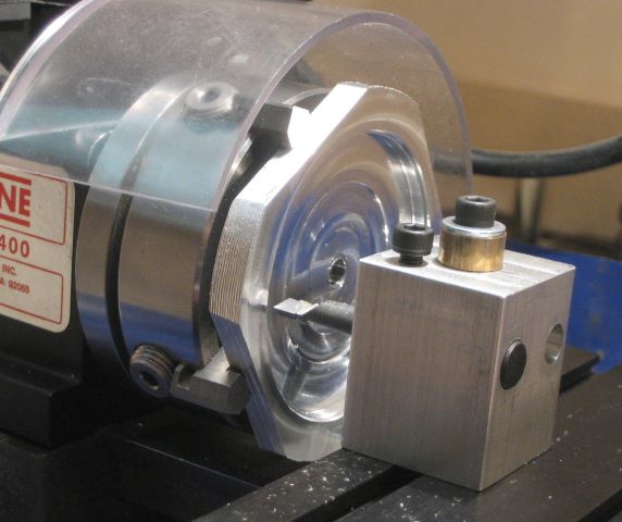
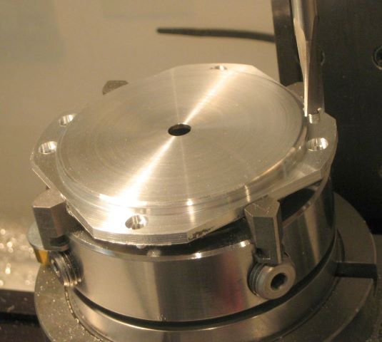
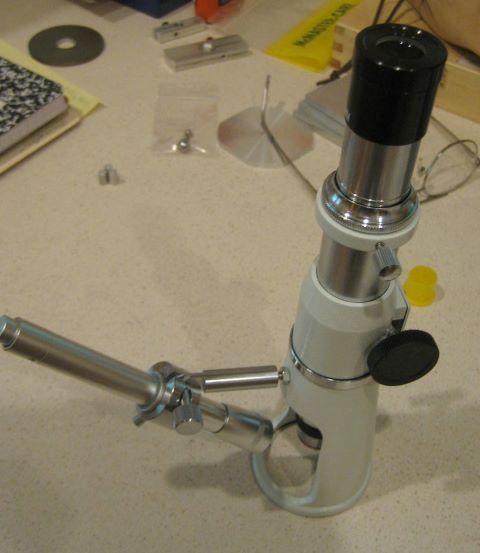
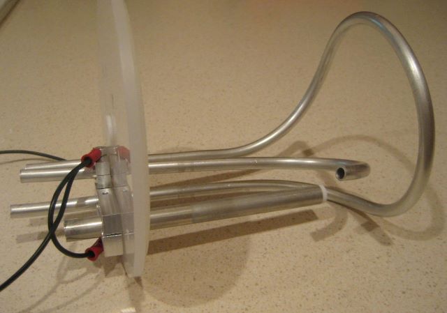
So here is the cover of my anodizing cell, with a faux spool end (i.e., a simple disk of aluminum) held by an expanding (spring) mandrel. The main post of the rack is titanium, but the last piece connecting to the disk is aluminum. This aluminum part will also become anodized and colored in the process. The cathode here is my “water cooled cathode” of the blog post immediately preceding this one.

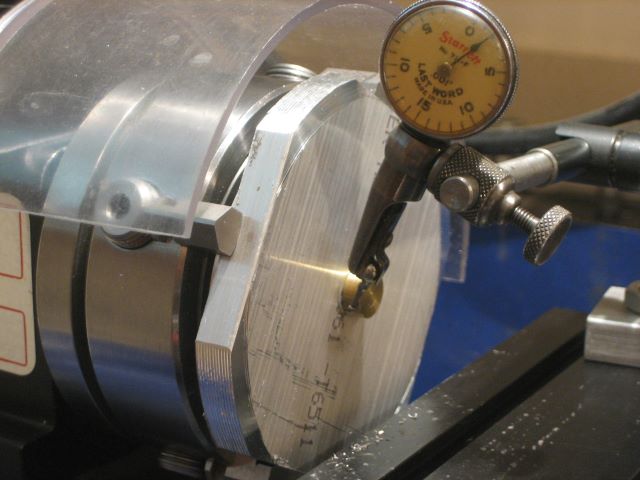
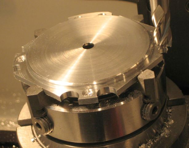
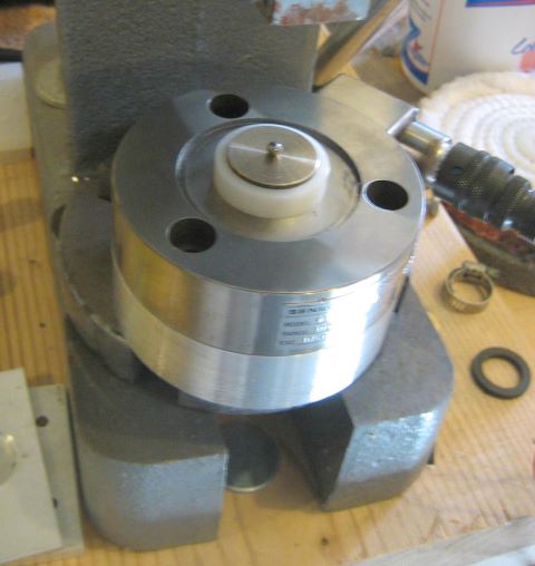
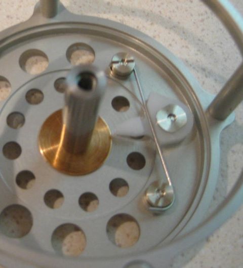
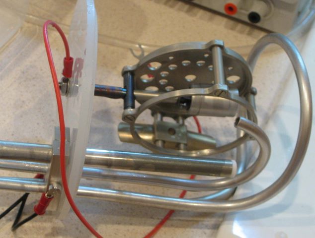
And this is the cover of the coloring cell, with the same disk and mandrel in place.

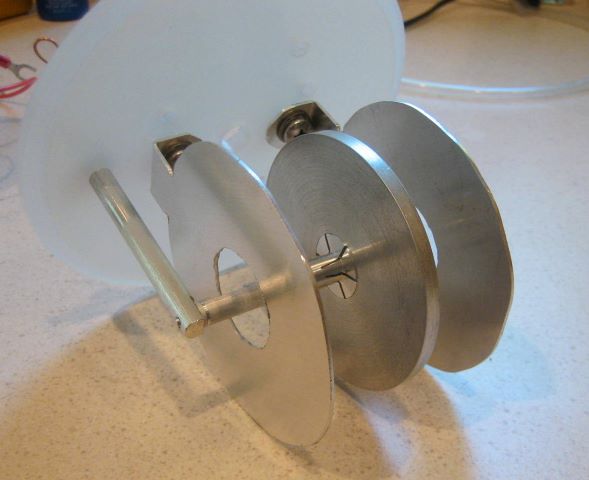
Note the two donut shaped counter electrodes. I expect these to impress a uniform electric field on the spool end/disk.

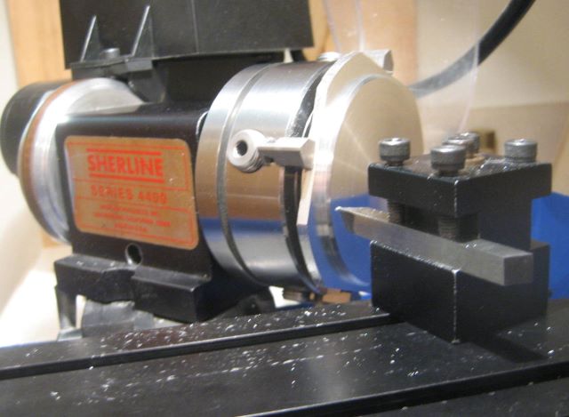
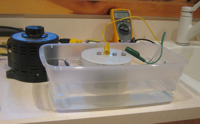
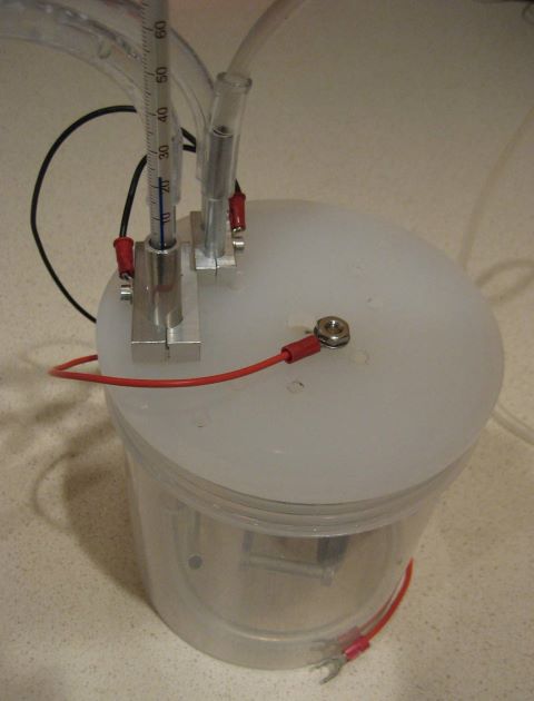
This is my AC supply, a variac and a doorbell transformer.

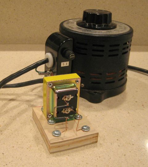
The variac is needed; I want 10 VAC but the “16 volt” transformer actually puts out 22 volts at no load. And I don’t know what current to expect.

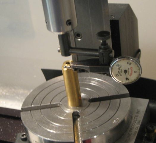
Here we see coloring in process. Ambient temperature on this day was 80 deg F, so I used a cold water bath to get the cell down closer to 68 deg F.

My process parameters:
Electrolyte is 10 g/l stannous sulfate plus 20 ml/l concentrated sulfuric acid. Balance is distilled water.
Run cell for 5 minutes at 10 VAC.
I was able to extract this information from the reference book and use it directly without having to do experiments.
My cell holds 24 fluid oz., so I used 7 grams of SnSO4 and 40 ml of battery acid (35% H2SO4) in one batch.
In this solution, the stannous sulfate is the source of tin ions, and the (mild) sulfuric acid attacks the anodize layer to allow electrical conduction.

Stannous sulfate has several advantages as a coloring agent, but one big disadvantage: the “stannous sulfate readily oxidizes to stannic sulfate” and then precipitates out of solution. I have no idea how long this takes. The proprietary part of commercial coloring electrolyte is the stabilizer, which keeps the tin in solution. By now, I can say that my solution is good for at least several hours.

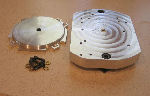
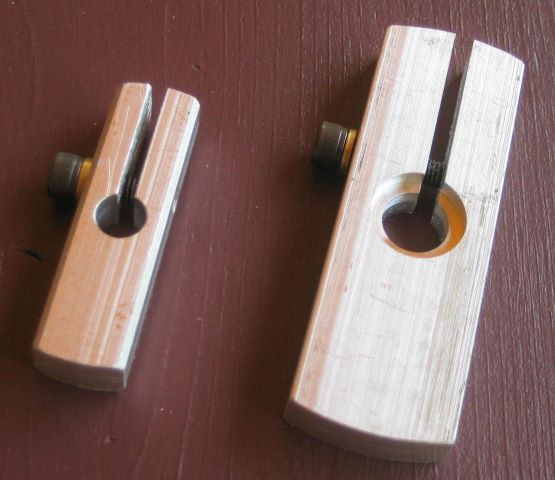
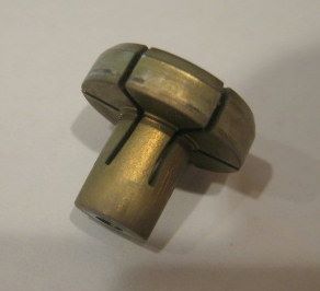
I did have one problem. My initial spring type mandrel did not provide a reliable contact for the anode. It worked the first time, but apparently I did not clean the part well enough and there was a streak of discolored surface. So I stripped off the anodize layer with lye and re-did the whole process. The second time through, anodizing was successful but the spring mandrel lost contact with the disk when I transferred to the coloring cell. The mandrel became colored but the disk did not. Here is a view of the spring mandrel, which I now think is not a satisfactory design.

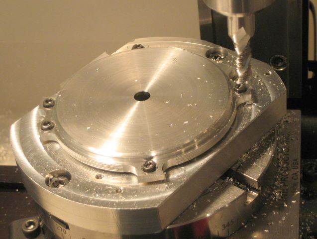
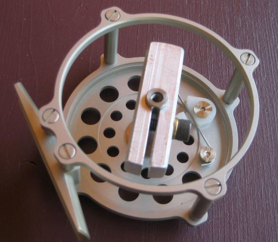
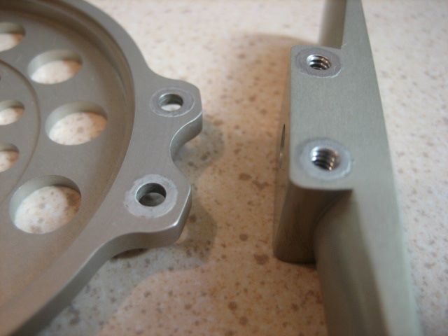
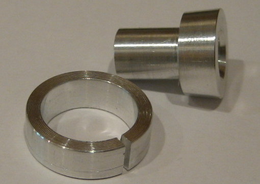
This is my improved design. The split ring fits into the bore of a spool end. Its inner diameter is axially tapered, exactly fitting the taper on the other part. These two parts are easily locked into the spool end bore with an arbor press.

Below is a successful coloring of the test disk.

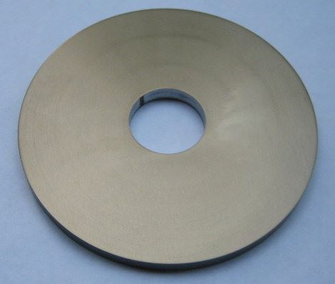
The surface area of disk and mandrel together is 14 square inches. During coloring, the AC current settles at 0.24 amp, after an initial surge of 0.75 amp. At different angles, the disk appears to have different coloring shades. This coating not like a dyed coating. I still find it difficult to get satisfactory photographs of the coloring.

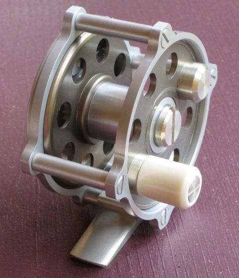
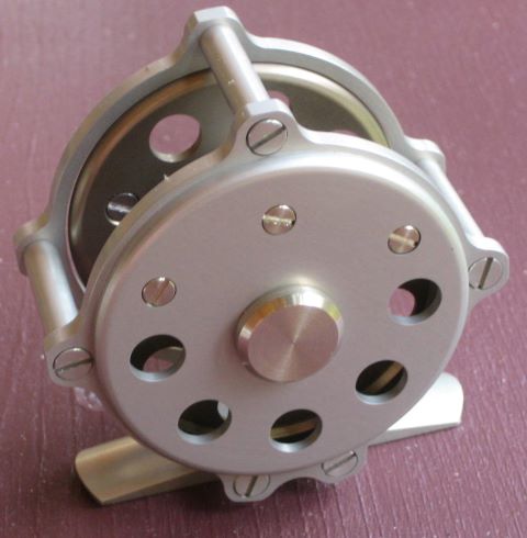
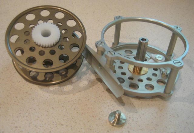
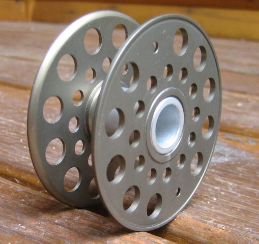
Finally, here is a spool with colored end plates.

Update 1 Oct 2012: I tried using a mixture of zinc sulfate and stannous sulfate, which is supposed to produce gray instead of bronze. But it was a bust. I still got “bronze”, and the coloring was uneven.
I was able to buy stannous sulfate from an Ebay vendor, as a lab reagent.
Another possible source for coloring electrolyte is Caswell. They sell a tin plating solution that is based on stannous sulfate. And, it includes stabilizer so the solution can be saved and re-used. It would need some added sulfuric acid.

Update 15 June 2020: I bought a 500g bottle of Tin Sulfate in 2012, and it worked for the next two years. Then I left it in a cabinet until now. I find that it has degraded and can no longer provide coloring.

Posted in Anodizing/Plating | 4 Comments

Water Cooled Cathode

When anodizing, power is dissipated in the cell and heats the water/acid electrolyte. The heat has two components, electrical resistance heating of the anode’s barrier layer and heat of formation of the oxide film. For example, if the anode area is 16 square inches then the current required is 1.33 amps (12 amps/square foot) and the voltage will be about 14 volts so the the electrical resistance heating is 18.7 watts. The heat of formation of aluminum oxide film is 140 BTU/(sq. ft. * mil) so putting on 1 mil of oxide in 1 hour is another 4.6 watts. The total power that must be removed to keep the electrolyte at constant temperature is 23.3 watts. If this is not removed, then 24 oz. of electrolyte will rise 53 deg F in one hour, and the process will not be successful.

The above figures describe the limit of my small anodizing cells when resting in an icewater bath at about 35 deg F. The walls of the polypropylene jar are good insulators, and conduct only about 23 watts of heat when the electrolyte is at 68 deg F, for a temperatue difference of 33 deg F. Earlier posts (1 Aug 2011, 30 July 2012) on this blog show the water bath setup. Sixteen square inches is smaller than a complete reel frame, so I have had to anodize reels as subassemblies.

To overcome the limit, but more significantly to eliminate the bother of extracting ice cubes from the refrigerator, I decided to try water cooling the cathode. I live in a rural area and so have a well supplying ground water. Here in August, the cold water is emerging at 54 deg F, 14 degrees below the desired cell temperature. Below is the cell lid/cathode assembly that I built.

Here you see a cooling loop of 3003 tubing, a J shaped tube (also of 1/4 inch 3003 tube) for air bubbling, and a plugged straight tube (6061 aluminum) that is a well for a thermometer. These are electrically tied together to form the cathode. The total surface area of the cathode is much less than 16 square inches, but I learned from a reference book that anodizing cathodes are typically about one third the area of the anode. The 3003 tubing is soft enough to be easily bent by hand. Air bubbling keeps the electrolyte from becoming thermally stratified; air is provided by an aquarium pump.

Here is the complete cell assembly (w/o electrolyte), with Tygon tubing for air, water supply, and water drain..

Before making the complete cell, I tested the heat removal capacity by cooling some hot water from the household taps. The cell temperature should show an exponential decay of temperature with time.

Here I have plotted a log function of the cell temperature in order to turn the exponential curve into a straight line. From this plot, I deduce that the heat removal capacity of the new cathode is 53 watts, for a ground water temperature of 54 deg F. In my new reel design, I need 2.44 amps to anodize the complete frame plus the spool hub. The heat to be removed is 43 watts.

Here is a picture of the anodizing in process. The plastic “shoebox” is no longer a water bath, but just a safety basin for acid drips.

With water running steadily, the electrolyte temperature fell slowly, perhaps 5 deg F in 20 minutes. I regulate electrolyte temperature by turning cooling water on/off.

Here I have extracted the lid/electrode assembly after 1 hour. Note that the 6061 thermometer tube has a dark deposit (which can be wiped off) but the 3003 tubes, having less alloy metal content, stay bright.

I have no instrument for measuring the oxide film thickness. But there are two ways to obtain some assurance that a film did develop. First, the film is an insulator (touch with the probes of a multimeter set to its continuity test function). Second, rings of conductive aluminum can be seen where the reel pillars touched the endplates and the foot.

And here is the frame and spool hub, completely anodized. I have not yet anodized the two spool ends because they will receive a different process.

Posted in Anodizing/Plating | 5 Comments

Aluminum Finishing

By now I have made enough reel parts of aluminum to have established a routine procedure for finishing. My goal is to arrive at a finish that is uniform but not highly reflective. If the aluminum is shiny before anodizing, I find that my sulfuric acid anodizing process tones it down.

Here are the steps in my process:
1. When machining, arrange to take a very light cut (say 0.001) as the last pass. This is particularly important when using lightweight tools such as mine by Sherline. A smooth machined finish eliminates much sanding.
Most of the frame parts are 6061 aluminum. A problem with this alloy is that small chips get picked up by the end mill and welded back onto the surface that was just cut. These can be sanded away, but it is easier to just take a reverse direction (i.e., climb milling) pass over the part with zero tool advance.

2. If end plates or spool ends are to have lightening holes (as illustrated above), do not put these in until a later step in the process.

3. If machine marks are still visible, wet sand with 180 grit until they are gone. Round parts are sanded while turning on the lathe.

4. Wet sand with 320 grit, again using the lathe.

5. Now add the lightening holes.

6. Vibratory tumble 2 hours with medium cut plastic pyramids and water. My tumbler is small, so I do one reel as 2 or 3 loads.
Note 5 Oct 2012: In regard to my “Fixed Spindle” reels, the smaller reel can be done as 1 load. It is the rear end plate of the larger reel that has to go into the tumbler by itself. A larger tumbler would solve this problem.

7. Vibratory tumble 2 more hours with very fine cut plastic pyramids. (If you do not have a tumbler, steps 6 and 7 can be replaced by wet sanding with 600 and 1200 grit. Just be sure to remove sharp corners.)

8. Wet sand with 2000 grit, this time hand held.

9. Wet sand with 3M Trizact (3000 grit), hand held. (This is the state of the parts in the photo.)

10. Clean well and anodize.

Update 3 Oct 2012: Step 8 can be eliminated; sanding with Trizact alone is enough after the tumbling. I cut an 0.75 by 1.5 rectangle of Trizact, sand one reel, then throw the pad away because it has visibly lost its grit.

Update 25 Nov 2012: I have been using the Trizact pad because I could not find wet sandpaper any finer than 2000 grit. The Trizact pad is grit bonded onto foam, and wears out rapidly when used on metal. Recently I visited a Hobby Lobby store and found an “Ultra Fine Waterproof Finishing Kit” that has sandpaper of 320 through 12000 grit. This item #0110 of Alpha Abrasives. You can see and order all their products here. Like any wet sandpaper, this is more durable than Trizact. To be fair, Trizact was not really designed for this application.

Posted in Abrading, Frame | Leave a comment