
This sheet metal and scrap sculpture was recently placed on the river bank downstream from where I live.


It is placed so that only a fly fisherman is likely to see it. I hope that keeps it safe from vandalism.
This sheet metal and scrap sculpture was recently placed on the river bank downstream from where I live.
It is placed so that only a fly fisherman is likely to see it. I hope that keeps it safe from vandalism.
If we were perfect fishermen, our reels would not need any provision for thrust loads on the spool (i.e., loads in the direction of the spindle axis). A fish on the line creates a torque on the spool, which we counter with an appropriate force on the knob. But we are at times likely to get a little excited when playing a fish and then apply extra forces on the knob that really are not needed to bring in the line. Typically these extra forces will be in the direction of pushing the spool into the frame.
In my first “fixed spindle” reel design, I included a bronze thrust washer in the frame, which ran against the face of the acetal ratchet.

But it was difficult to make the two faces of the washer parallel. I made several different fixtures to assist in this, but none were totally satisfactory.
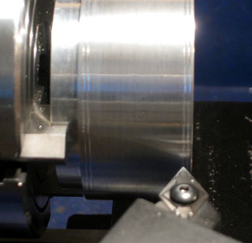
When I created my most recent reel design, I left out the thrust washer. Now the thrust bearing is a raised face on the ratchet, running on the anodized inside end of the frame.
Is this OK? I had to devise a test to help convince me.
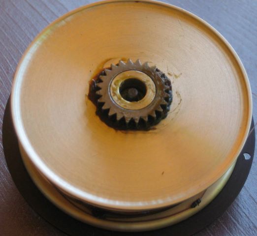
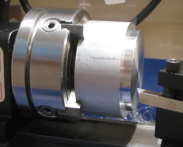
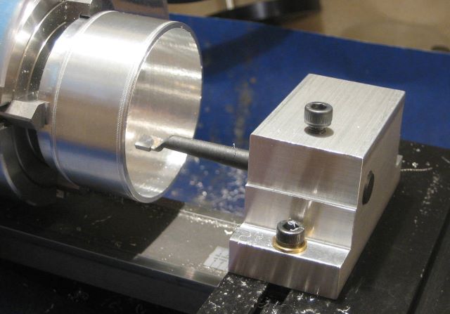
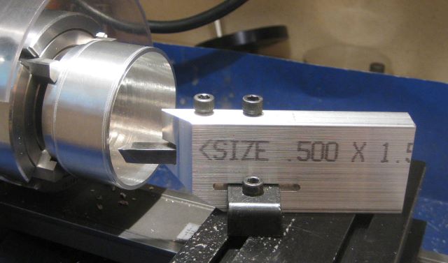
Here is the fixture for my test. On the right is an anodized plate supporting a short spindle. On the left is a 200 rpm gearmotor with an acetal runner attached to the shaft.

Where the two bearing surfaces meet, the aluminum was wet sanded to 2000 grit before anodization, and the acetal was sanded to 12000 grit with Micromesh pads.
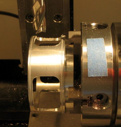
Here the fixture is assembled. The gearmotor weighs 2.3 pounds and provides the thrust load for the test. A piece of wire carries the necessary torque.

I ran the fixture for 4 days, over one million revolutions, and the anodize coating remained intact. Had it broken down, it would have been visible and it would have conducted electricity. My conclusion is that this is an adequate thrust bearing.
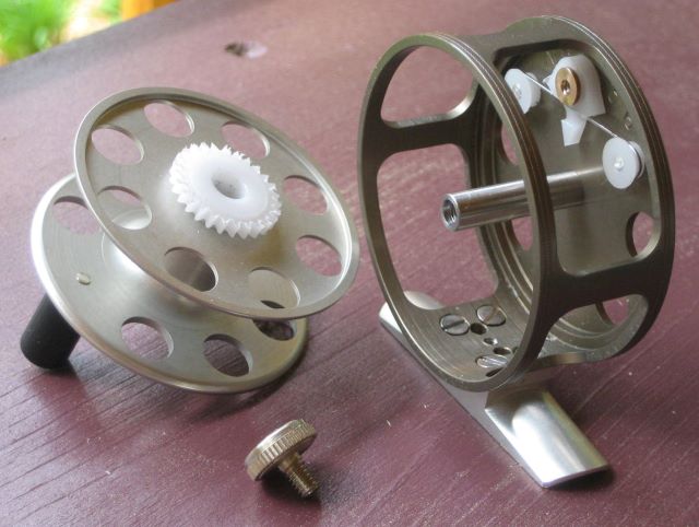
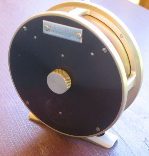
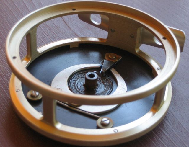
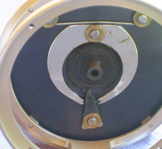
I met Chris of Shenandoah Rods at the recent Grayrock gathering. After he saw pictures of the 1 weight reel that I recently made, he sent me these photos of a small reel in his possession.
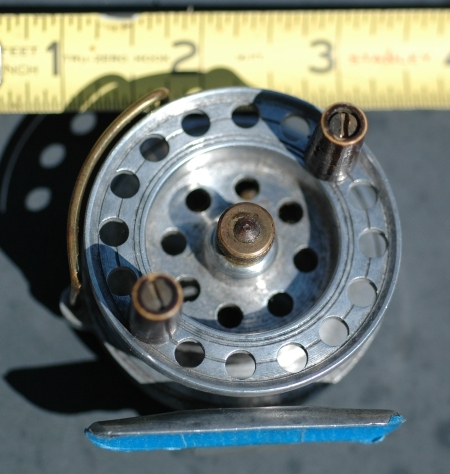
Unfortunately, we don’t know who made it.

It has several interesting feaures, so I wanted to make a record of the design.
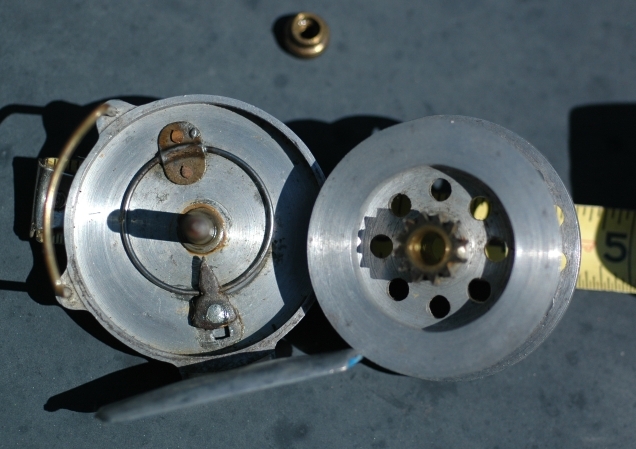
I would call this a “frameless” reel, having only a back plate and a line guard for a frame.
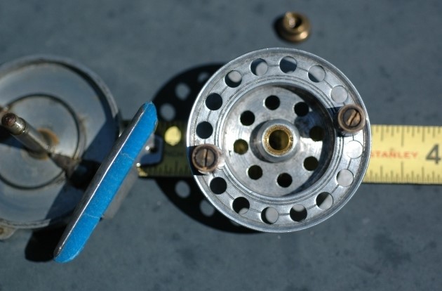
Some notes:
Aluminum has not been anodized.
Copper and ferrous alloys in direct contact with bare aluminum.
I try to avoid both these conditions, but here we see that they have not affected function.
Incidently, Chris gave a talk on rod ferrules that I found to be highly instructive. You can find his slides here.
You should read this even if you do not plan to fit ferrules any time soon. It is an education in making close fitting parts.
Steps:
1. Make female round and uniform using a homemade brass mandrel and abrasive powder.
2. Make the male round and uniform with an external hone (Sunen).
3. Trim the male O.D. using pillar files (Grobet).
I keep a shaft collar clamped on the rear spindle extension of my lathe. It provides a grip for a small “gear puller” that I use to unlock MT1 fixtures from the spindle.

The only time that I remove the collar is when I am cutting screws and need to turn the spindle by hand, while cutting the thread with a die. Then I install a clamp-on crank.
The problem with this is that screw making involves alternation of motor powering (cutting the screw diameter) and hand powering (thread cutting). I do not want the crank flying around under motor power, so I alternately attach and detach the crank, over and over again. A tee handle driver is required each time. I often forget where I last set it down (age factor), so additional time is lost in search.
My “fixed spindle reel”, of which I have recently made ten, requires 15 screws.
I have now made a new crank, one that slips over the shaft collar.

It drives the collar, and therefore the spindle, by two axial pins that fit two holes drilled in the collar.

So now I never remove the collar and never have to find the tee driver. I just have to remember where I last set down the crank.
Now that this innovation is in place, I am developing a new reel design that has only three fabricated screws.
I find that high speed steel (HSS) lathe bits cut more smoothly than any carbide bits, brazed or insert. HSS bits cut best when freshly sharpened, a task that I have dreaded.
My grinder is typical of the “home improvement store specials”, having a 6 inch diameter aluminum oxide wheel, grit 60. The tool rest is almost useless for lathe bit grinding. The angle that it can be set is indexed by serrations on two mating parts, and the serrations are much too coarse (15 degree steps). Also, it has a groove running diagonally (for drill bits?) that is quite inconveniently located for my purposes.
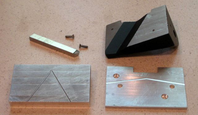
I made a 1/8 inch thick aluminum plate to permanently screw onto the standard rest. Now when I lay a 1/4 inch tool flat on the new surface, I get a 7 degree relief angle. I engraved some diagonal lines on the new plate to indicate a 10 degree side angle. The rest is now handy for grinding lathe bit sides and tops.
In order to get a larger relief angle on the end of a bit, I also made a 3/8 inch thick plate that can be set on top of the 1/8 inch plate. It is located by two pins. The engraved lines on this plate are at 60 degrees.
Now I can grind all 3 surfaces on the bit at correct compound angles by holding the tool flat against a tool rest.
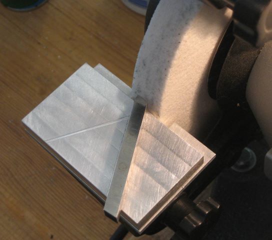
This makes the sharpening task much easier, and should cause me to do it more often.
Update: See post of April 29, 2020 for a simpler fixture and improved grind pattern.
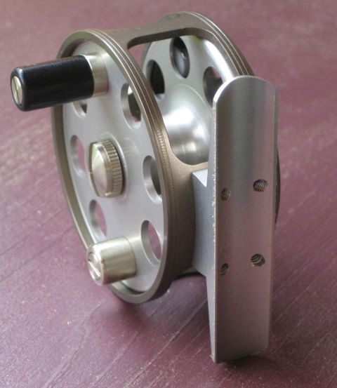
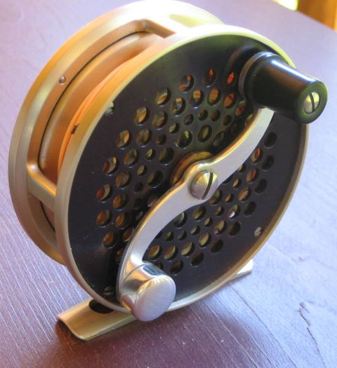
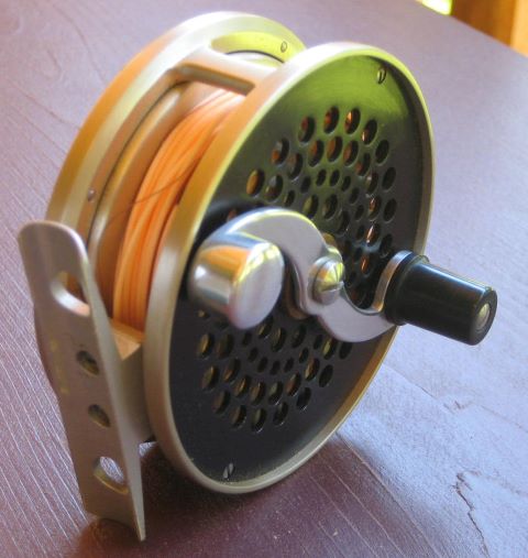
This reel is for a friend who is making a 1 weight rod. The reel is 2.3 inch diameter and weighs 2.6 oz. It uses the one piece spool and one piece frame from recent posts.

In a post of 10 May 2013, I included a table of reel spool sizes for WF lines of sizes 0 through 5. This is really a “Size 2” by the table; we wanted extra room.

Both the spool and frame are anodized aluminum; the frame has also been electrolytically colored.


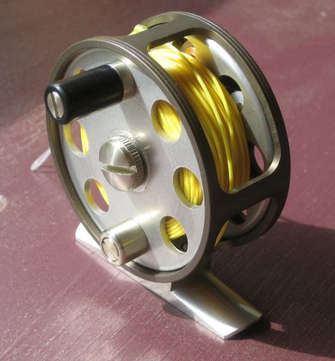
In this last picture, a WF1F has been loaded.
This reel belongs to a friend who has long had a cabin in the North Branch, but well downstream of where I live.
He put it in my hands because the click had become weak. I found that the spring had taken permanent set, and was able to restore the click strength by just straightening the spring wire. I cannot be confident that this is a permanent fix; I believe that the spring is overstressed.
The Grayrock meeting of bamboo rod makers was held in Lovells last year, and again this year. So I attended even though I am not making rods.

Wes Cooper

Wayne Cattanach

Judging tapers
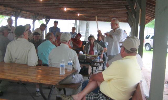
Outdoor session
My interest in making a rod is now piqued. Approach being considered: nodeless, one piece, impregnated rather than varnished.
To go with the one piece spool, I have also made a one piece frame. This is a record of the steps.
Face the material on both ends and cut a “grip”, a projection for holding the work in many coming steps.
Groove the finished OD to enhance the milgrain pattern.
(Update 14 Nov 2013: In the above picture, I am making two closely spaced grooves with a sharp tool and will then press the milgrain tool into the narrow land in between. It turns out that the resulting pattern is partially erased when the part is later tumbled in abrasive media. I have found that the milgrain pattern is better preserved if it is made at the bottom of a groove. My milgrain wheel is .048 inch wide, and a groove .052 wide and .010 deep works well.)

Apply the milgrain.
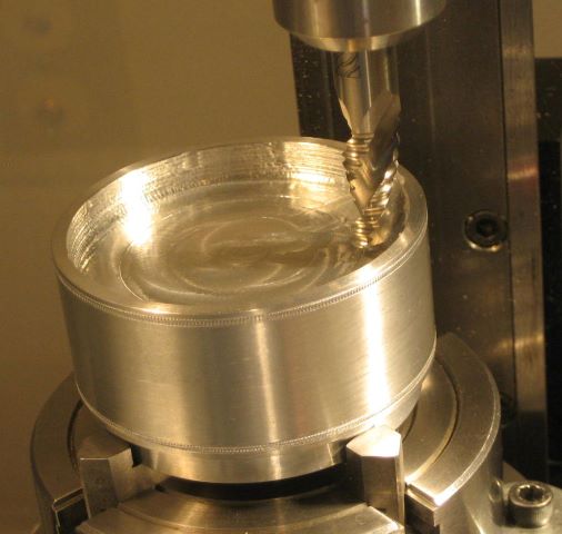
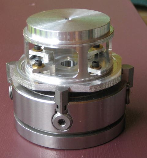
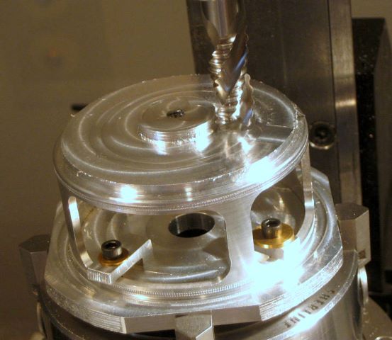
Hollow out the inside with a roughing end mill.
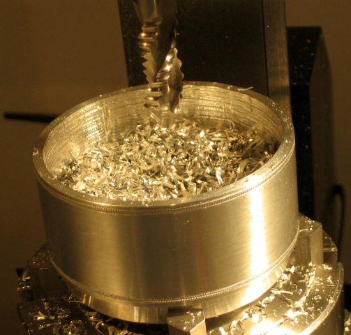
Working in the vertical position causes chips to accumulate. I may try to do this in a horizontal position the next time.
Turn the ID with a boring tool. This tool is too long and skinny to make a good finish.
Turn a finished surface on the bottom. I made a special tool post to get the bit deep enough.
Mill out the “windows”. This creates sharp edges that I do not know to remove, except by tumbling in abrasive media. My skill with a file is not adequate to do the job.

Drill and countersink holes for foot mounting.
Finally the part can be unchucked from the “grip”. Here I have fit it to a grooved tool plate in order to work on the back.

Trimming back with a roughing end mill.
Continuing with a ball end mill. This is followed by turning.
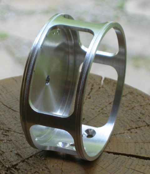
This is the finished part, not yet ported, tumbled, or anodized.
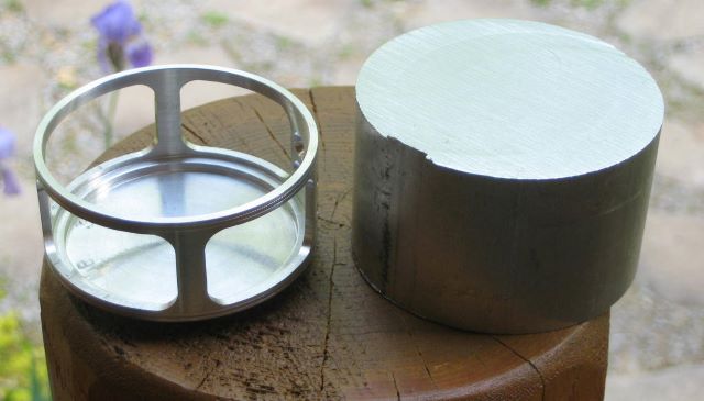
The material weighed 11.7 ounces, and the finshed part is 0.77 ounce. So 93 % of the material was turned into chips
Lovells rodmaker RKP decided to make bamboo rods with pentagonal cross section, rather than the usual hexagonal. And now that he has started, he says that it takes less time to plane 5 strips than to plane 6 (!).

The down side is that he had to buy 2 planing forms instead of just 1 because the shape of each strip is an isoceles triangle (72, 54, 54) instead of equilateral (60, 60, 60). You have to have separate forms for the right and left hand sides of the strips.
When setting up the planing form for a hexagonal rod, it is usual to employ a dial indicator with a conical 60 degree point. Obviously, that won’t work on the two penta forms.
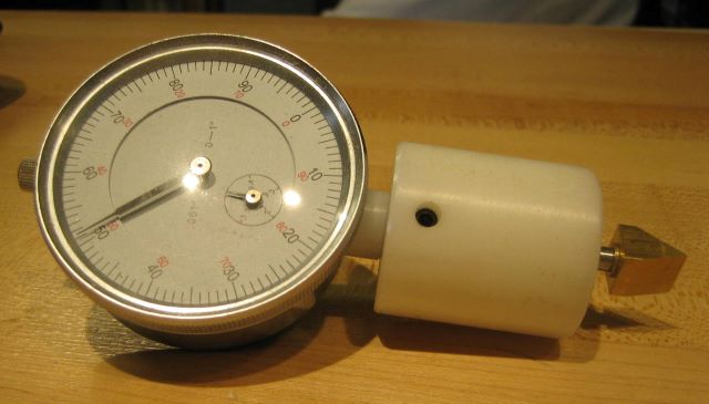
So I made him a special tip for his dial indicator, with sides sloping 18 and 36 degrees from vertical.
