MiniLathe Tooling

In 2015, I replaced my Sherline mill with a MiniMill (Little Machine Shop 3990).

The switchover was simple; I only had to make some special hold down clamps to continue using my Sherline rotary table with the new mill.

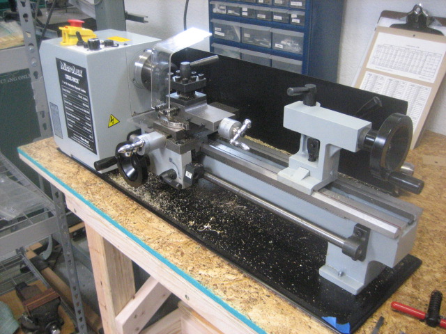
Now I have gone a step further and bought a MiniLathe. I chose MicroMark 84631 because it has 20/inch leadscrews on the cross slide and compound.

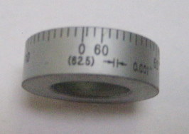
I locate the cutting tools by reading the dials at the handwheels, and I cannot work with a dial that has 62.5 divisions.

During lathe assembly, my attention was drawn to the system for adjusting the carriage gibs. It uses a combination of screws to push and pull the gib. None of these screws can be properly tightened because there is no solid stack of parts to tighten against.

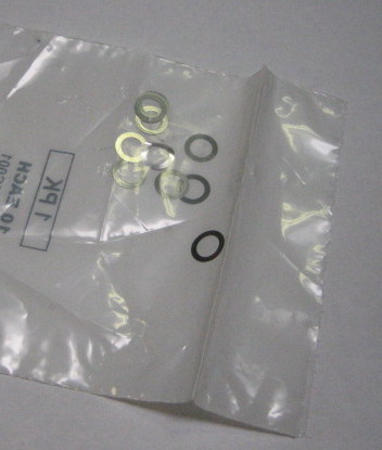
So I removed the “push” set screws and put round shims under the gib and around the “pull” cap screws.

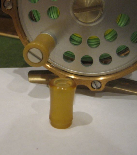
The tool post can clamp a bit as large as 5/8 inch, but you would have to do a lot of grinding to get the point down to the right height. I have many 1/4 inch bits from my Sherline lathe that I will continue using.

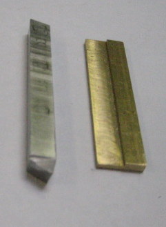
The brass shim here brings a 1/4 inch bit up to working height, and the shoulder centers the bit under the clamping screws.

It is obvious that the 3 inch chuck for the new lathe is more robust than the Sherline 3 jaw chuck.

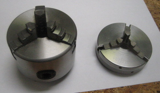
But this extra heft comes at a price. Changing chucks is a matter of fiddling with studs and nuts in a confined space, rather than just spinning the chuck onto a spindle nose thread.

Further, I am heavily invested in Sherline chucks.

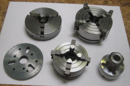
Significantly, the 4 jaw chucks can serve as milling vises, and can be quickly transferred to the rotary table on my mill. So I am highly motivated to continue using my Sherline chucks.

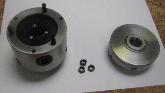
My solution is to buy an ER-32 collet chuck from Little Machine Shop. This allows me to chuck stock of up to 3/4 inch diameter through the hollow spindle.

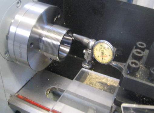
When I first installed the collet chuck base on the spindle, I found the TIR on the taper to be about .0001 inch. Then I chucked a gauge pin and read about .0002 inch TIR. (Note 9 April: Apparently this was luck. The second bolt-on measured .002 TIR on the taper. Later same day: I made several installs. One position consistently has .002 TIR, another .001, but the best position is under .0003 .)

The key to using my Sherline chucks is to leave the ER-32 chuck in place and make an adapter with the Sherline 3/4-16 thread.

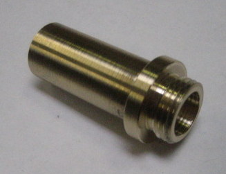
This adapter is Duronze. It has 3/4 inch OD and a bore of a little more than 1/2 inch. Sherline sells a similar adapter but it does not have a bore.

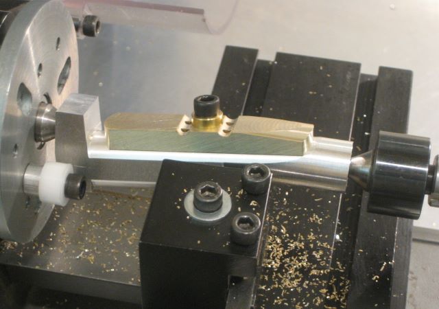
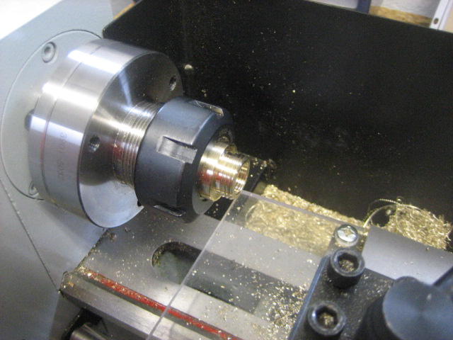
Here is the adapter installed.

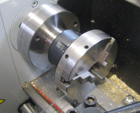
And here is a Sherline chuck mounted.

To keep chips from falling where they may, I tape transparency film to the stock chip guard and I have installed a piece of acrylic sheet in front of the carriage.

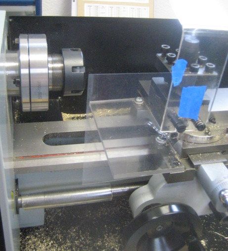
Note also a piece of Tygon tubing (split) around the exposed lead screw.

From LMS I bought several accessories: Jacobs chuck, live center, die holder, hand crank, and cut-off tool.

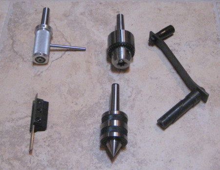
With all this, I believe that I have replaced all the Sherline lathe functions except for knurling.

Posted in Tools, Turning, Work Holding | 1 Comment

Cool Water

He’s a devil not a man,
and he spreads the burning sand with water.
Cool, clear water.
“Cool Water” recorded by Sons of the Pioneers (and many others)
Songwriter Bob Nolan

Got my anodizing process restarted after the move to New Mexico. This involved adding some plumbing to a garage utility sink for the cooling water loop.

One of the desired conditions for sulfuric acid anodizing is a bath temperature of 20C (68F). The DC supply is injecting power into the bath and the production of aluminum oxide is exothermic, so the bath is likely to rise in temperature during the 1 hour process time. If I would make a bath of 1 gallon or more volume, the bulk of the acid/water solution would limit the temperature rise. But I use only 1 quart of solution, making forced cooling necessary. My blog post of 22 Aug 2012 details the water cooled cathode.

In Lovells MI, my well water came out of the ground at 4 to 12 deg C year around (pump setting 50 ft, water table 1 ft). Overcooling was quite possible, so I had to supply the cooling water intermittantly while watching a thermometer. Probably made an on/off cycle every 5 minutes. Running the process took constant attention.

Here in NM we have been having warm weather for the season, 75F for several days. I am on city water, and the houses here are built on a slab. I do not know the building practices, but it seems that there is not much insulation between the cold water pipes and the concrete. When I first open a cold tap, the water may run at 24C for a while, gradually dropping to 18C. So there is not much temperature difference available for cooling. With a steady flow through the tubes, I could only keep the bath temperature down to 23C. Having more tubing in the cooling loop would probably allow lower temperature.

As for the resulting anodize layer, I cannot observe that it is adversely affected by the slightly higher temperature. And, I spend much less time watching the thermometer.

Another process consideration is that here at 5800 ft elevation, water boils at about 200F. So sealing the anodize layer has to be done at the lower temperature. My data sources say that anything above 170F should be OK, see blog post of 3 March 2012.

Update 23 May 2017: Resolution is to put a submersible aquarium pump, frozen blue ice packs and water into a small insulated container. Use the pump to run a closed cooling loop. With cooling water at 14C, I was able to maintain cell at 20C. I did stabilize the cell solution near 20C before starting.


Posted in Anodizing/Plating | 1 Comment

Bronze Frame Reel – Final

The last drawing covers all the remaining parts for the click mechanism.

The kink in the spring biases the pawl for left or right hand wind. There is a blog post on spring bending, 13 June 2016.
The “pawl shim” is just a washer that spaces the pawl away from the back plate. It is supposed to help the pawl move freely. Info on this part was posted 8 May 2014.

Finally, here are material lists for the two reel sizes.

Posted in Plans, Spring | 2 Comments

Bronze Frame Reel – Pawl

The clicker has taken me more development time than any other reel feature, except possibly for the aluminum anodization process. I started out thinking that the pawl should be made from steel, since that is what I observed on commercial reels. I bought a “test kiln” so I could quench and temper.

Then I made a life test fixture, using a gearmotor.

I soon learned that modern plastics such as Delrin are much more durable than steel, in this application. I think it has to do with impact absorption, or “toughness”. Blog reference: 23 Aug 2011.

This is the present pawl configuration, a symmetrical pawl and an asymmetrical spring on symmetrical mounting posts.

Prior to this, I had made either the pawl or the spring posts asymmetrical. This recent configuration is the easiest for changing from left hand to right hand wind.

Here are the drawings for two sizes of pawl.


Notice the 20 degree angle on the flanks of the pawl tip. This is the pressure angle of the mating gear. It is not important when the pawl is clicking along in one direction, but it does help the pawl make a smooth reversal of direction.

Blog post on pawl fabrication: 22 Jan 2014.

Posted in Pawl, Plans | 1 Comment

Bronze Frame Reel – Ratchet & Bushing

The bushing and ratchet are made as one piece. I have not tried gluing two pieces of Delrin together because I don’t know of a suitable glue, and I have concerns about concentricity.

Terminology: Is it a ratchet if it allows rotation in both directions? It is made with a gear cutter, but is it a gear if it does not mesh with another gear? “Clicker wheel” might be the best term.

For the 3 weight reel, the part has a somewhat different form; there is no recess in the face of the gear (ratchet, clicker wheel, etc.). The reason is that the gear end of this part also serves as a thrust surface, and a recess in the 3 wt. part would be too small. All this leads to a different spindle mounting for the two sizes of reel.

See the post of 7 April 2016 for step-by-step instructions on making this part.

Posted in Bushing, Plans, Ratchet/Gear | Leave a comment

Bronze Frame Reel – Knob

Here is the knob and its mounting hardware. The purpose of the pan is to keep leaders from getting wound around the pin, under the knob.

The 5-40 thread on the pin has to be cut as close to the shoulder as possible – use a hex repair die as explained for the Spindle.

I have been making knobs from Ultem, a polyetherimide (PEI). It is available as plain resin (translucent) or glass filled (opaque).

My blog post of 11 May 2015 considers cutting the 1.8 inch radius.

Posted in Knob, Plans | Leave a comment

Bronze Frame Reel – Spool

Recently I have been making spools from a single piece of aluminum, even though it takes a lot of time to remove all the waste material.

An advantage of using aluminum is its light weight, and the most significant aspect of this is low rotating inertia. This directly affects the click; pawl-to-ratchet forces are reduced. (The purpose of the click being to prevent spool overrun, not to fight fish.)

A disadvantage of aluminum is that you probably should anodize. This blog has many articles on anodizing, use the Categories list at right to locate. The anodizing cell can be as small as 32 fluid ounces if you are careful about cooling and agitation.

It is certainly practical to piece together a spool and the waste will be much less. Good adhesives are available (see 27 Aug 2010). You need a fixture to be sure that it goes together square (see 23 Nov 2011).

So here are the drawings for spools of two sizes.


I have omitted some of the porting on the face to serve as a counterweight for the knob.
Past blog posts on the spool are 13 Feb 2015 and 1 June 2013.

Posted in Plans, Spool | Leave a comment

Bronze Frame Reel – Spindle

I make spindles from stainless shaft material that is already ground to a fine finish.

It is important that this part screws all the way into the Rear End Plate. There is a thread relief counterbore in the plate, but the spindle male thread must run as near to the shoulder as possible. I have an 8-32 hex repair die that has a tapered opening on just one side. After cutting the thread with a round die (which is tapered), I run on the repair die with its untapered face leading.

This drawing also shows the oversize screw that secures the spool. Alloy c792 is a highly machineable 12% nickle silver. Its male thread needs the same treatment as the spindle. I have been making the “spherical” radius by cutting a couple of cone surfaces and then working over with a file. The slot is just wide enough to accomodate a newly minted U.S. quarter.

Posted in Plans, Screw, Spindle | Leave a comment

Bronze Frame Reel – Pillars and Screws

I have been making pillars from nickel silver. The two pillars that fasten to the foot have cross drilled holes that are off center. This helps balance the Front End Ring with the heavier Rear End Plate.

I buy 18% nickel alloy from suppliers that cater to knifemakers. I don’t know for certain that it could be certified as c752. On Line Metals now offers 12% nickel alloy c792 in diameters as small as 3/16 inch. This would also be a good choice. For the highly machineable c792, I would make the tap holes with #47 drill.


I make the frame screws from standard pan head screws, modified by turning the heads to a smaller diameter. Turning also improves the concentricity of head to thread. The turning fixture is a rod that is drilled and tapped at one end.

Posted in Frame, Plans, Screw | Leave a comment

Bronze Frame Reel – Foot

The foot is made mainly by milling operations.

The challenge is sequencing these operations so that the part can be clamped.

Only recently did I figure out how to cut the top surface with my lathe.

Earlier posts on the foot:
24 July 2016, 11 June 2015, 28 July 2014, 14 Feb 2012.

Posted in Foot, Plans | Leave a comment