The gearmotor that wasn’t a gearmotor

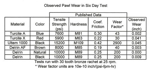
First of all, I must say that the pawl test data that I previously posted (Aug. 22, 2010 : Results of Pawl Wear Test) cannot be relied upon. I now realize that the “gearmotor” that I used for this test may have been misoperating. This post explains why the data is suspect.

Yesterday I intended to start more ratchet/pawl wear tests. I made a new ratchet. As I fastened the new ratchet in place, I noticed that I could manually turn the output shaft of the gearmotor in one direction, but not in the other. This is peculiar behavior for a gearmotor. Then I engaged a pawl and plugged the motor into an outlet. To my surprise, the gearmotor did not rotate, but did make its usual buzzing sound. I unplugged the cord, wrenched the output shaft around a little, and plugged the cord back in. This time it rotated, but stopped after a few seconds. Time to find out just what this “gearmotor” is.

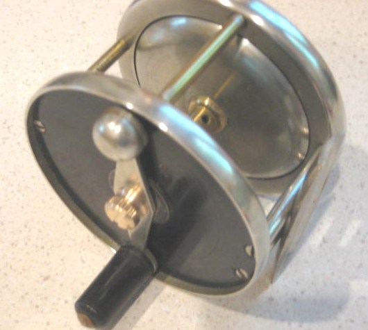
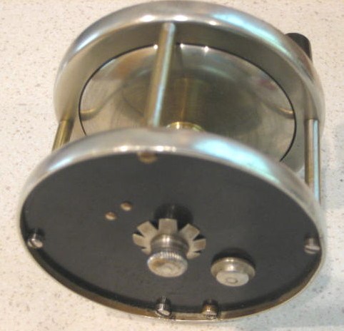
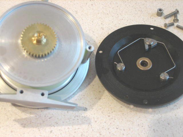
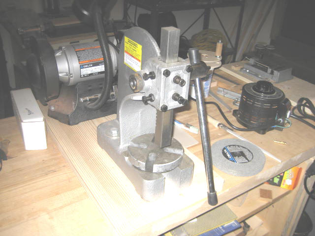
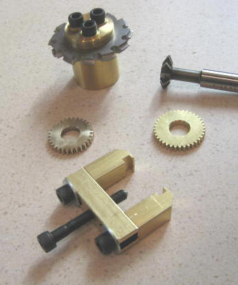
Here is a view of the inside parts of the motor.

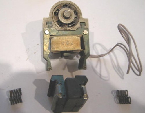
Around the shaft are two sprag clutches. Each is fixed to a moving magnetic armature with limited rotation, and each armature has two springs that push it toward a central position. (These two swinging armatures stack axially on the shaft and are difficult to see in the photo.) A separate fixed armature part incorporates a ceramic permanent magnet. Under 60 Hz excitation from the coil, the two moving armatures vibrate in phase opposition (?), and the two clutches cause the output shaft to turn (at least some of the time).

The problem with the wear data that I have already posted is that I cannot be certain that the motor was turning throughout each of the six day tests. The sprag clutch drive now operates intermittantly; I cannot say how long it has been this way. Certainly the motor did work part of the time, or no wear would have occurred with any of the materials. The Delin pawl that shows zero wear was not the last one tested.

In retrospect, I can see several reasons to have had earlier suspicions about of the “gearmotor”. It was the cheapest and most compact gearmotor available (too cheap, too compact to be real). It made a humming sound that I would not expect from gears meshing, and with time, the sound became a buzz that gradually drown out the sound of pawl on ratchet.

I do know that I was getting rotation at the start of each test, and I may be overly cautious in now declaring the data to be suspect. But it bothers me that the wear results obtained have no correlation to material properties. It would be much more satisfactory if wear lined up with coefficient of friction, or perhaps with hardness.

So there is nothing to do now but obtain a real gearmotor and repeat the tests.

Posted in Click, Pawl, Testing | Tagged , | Leave a comment

Loctite Assembly of Spool

My first reel design has a multi-part spool: anodized aluminum for the spool ends and copper alloy (bronze) for the shaft. I could have saved weight by using an aluminum shaft, but I could not reconcile myself to having aluminum as one element of a journal bearing.

So, how to fasten the spool ends to the shaft? A press fit would be simple, but requires tolerances of 0.1 thousandth on both shaft diameters and spool end holes. My capability is more like 0.5 thousandth. So I made the parts for my first reel with about 0.001 to 0.002 inch diametral clearance, then knurled the shaft. Assembly with an arbor press was easy.

While making the knurls, I found that 360 brass does not form well. So I changed the shaft to 544 bronze. It is also leaded and machines easily, and is probably more corrosion resistant.

Then my (mechanical engineer) nephew brought up the consideration of galvanic corrosion. Aluminum and bronze are widely separated on the galvanic scale. The anodize coating should protect the aluminum in many cases, but I am sure that the knurled ridges on the shaft break through the thin (though hard) anodize layer. My first reel has not corroded, but it is only a couple months old. I want to make more reels but cannot wait years to find out if I have a problem.

So I decided to try Loctite. It would allow the anodize layer to remain intact, and at the same time exclude electrolytes from the joint area. I consulted Loctite’s technical advisors and they recommended 3 alternatives, which are (in order of increasing strength): Loctite 243 (threadlocker), Loctite 2760 (higher strength threadlocker), Loctite 609 (retaining compound) with 7649 primer. I decided to try 609 first.

Before committing real parts to the process, I made 3 sets of cylindrical test parts. These have the same mating surface diameter (7/16) and axial engagement (0.180) as the reel spool parts. They also have tapped holes so that eye bolts can be attached. Diametral clearance is 0.001 to 0.002, and the aluminum is anodized as described in a May 4, 2010 entry of this blog. I used the primer only on the aluminum part. After 3 days of cure, I was ready to test the joints for strength. If the joints would hold 50 pounds or so, I would consider them adequate.

(Point of clarification: All three test items were glued with Loctite 609. I did not test either 243 or 2760 threadlocker.)

Here is my pull test setup, on a post in my pole barn. I bought a 110 pound (50 Kg) spring scale on Ebay and used a large turnbuckle to apply the load. I put a small frame of drilled bars and bolts around the test article so parts would not go flying if the joint broke. All 3 test assemblies held at 100 pounds.

Later, I was able to easily break the joint with my arbor press, so rework of the assembly is possible.

Posted in Bonding, Spool, Testing | Tagged , | Leave a comment

Results of Pawl Wear Test

Some background for this post is in a discussion on Rod and Reel Maker’s Forum.

The discussion made me think of using plastic for the pawl. (In my reel design, replacing a worn pawl takes only a screwdriver, for backplate removal.)  Also, about the same time, I had a meeting with Michael Hackney wherein he suggested that pawls may benefit more from low coefficient of friction than from hardness. I decided to try a harder ratchet and to conduct tests to compare different pawl materials under controlled conditions.

Two things to decide are how long to run the test and how to measure pawl wear. I needed a few preliminary tests to help decide these issues.

I made the first test pawl from 6061 aluminum. After running only a few hours, the pawl was no longer effective. It was notched on its flanks (from striking ratchet tooth tips) but was also shorter than its starting length, preventing proper engagement with the ratchet. This suggests using pawl length as a measure of wear. The flank notches are obvious, but I could not determine a way to measure them.

My second test pawl was plain, natural Delrin. I ran it for 2 weeks and it was still going strong, with no obvious length change. This was encouraging, but it did not help me to decide a practical duration for the test.

The third pawl was Ultem 1000 (a harder plastic). I would have tried PEEK or Torlon, except for cost. At six days, the sound emitted from the test fixture had obviously changed. I stopped the test and measured pawl length (this time I had remembered to measure at the start of the test). It had lost 0.045 inch in six days, and so was near wear-out (whole depth of the ratchet teeth is 0.060 inch). My test duration would henceforth be six days.

Here is the test fixture and a rainbow assortment of pawls.

I ended up testing 6 plastics, including a re-do of natural Delrin at 6 days. Here is a chart that shows the materials and the measured wear, in terms of pawl length change. I have also given some data on mechanical properties, but these are from a variety of sources and may not be consistent.
(Sept. 6, 2010 : A fault has been discovered with the gearmotor used for these tests. Read further on this matter in my post of today. The wear data in the table below cannot be trusted.)
(Nov. 16, 2010 : I have now completed a second set of pawl wear tests, using a real gearmotor. The results are not greatly different. See the new post of this date.)

So why did natural Delrin do better than black? What is the most important property: strength, hardness, or coefficient of friction? It is difficult to draw a general conclusion.

If anyone would like to compare another material, please provide me with a material sample (a disc 0.125 thick and 0.75 diameter would work) and I will make the pawl and run under the same conditions.

I would like to use the fixture to study plastic ratchets with metal pawls, but don’t know how wear could be measured.

Posted in Click, Pawl, Testing | Tagged , | 1 Comment

A Reel Vom Hofe

My friend Steve owns an original fly reel by Julius Vom Hofe (brothers Edward and Julius both made reels). This is the style of reel that I have adopted, but with modern materials. His reel is in very good condition, as the hard rubber side plates are not cracked.   I believe that this reel is about 100 years old. On the click end plate the engraving is partly obscured, but I can stiil read “Julius…Pat…Oct…Brooklyn”.


The crank securing screw is missing, so I am trying to make a suitable replacement. My bronze prototype is seen in the first photo. When he and I agree on form, I will make another of nickel silver.  This reel is 3.0 inch diameter and 1.9 inch width across the rings.  Weight is 8.5 ounces.  Because I have substituted aluminum for nickel silver, my reel is 5.5 ounces.

Posted in Classic Reels | Tagged | 1 Comment

Grayrock 2010

Grayrock is a meeting of bamboo rod makers held annually near Grayling MI. I have never attended (since I am not a rod maker) but a friend is on the program committee. He recruited me to be the novelty speaker for this year, on the subject of reel making. Following is my slide show presentation.

This is the only reel that I have made so far. It has the general appearance of a Vom Hofe reel but uses aluminum and Delrin instead of nickel silver and hard rubber.

Here is the working mechanism, a ratchet and pawl drag. There is no way to disengage the pawl, but it is asymmetrical for more resistance to outgoing line.

These two books are my only education on machining. They are both oriented to Sherline lathes and mills, which is what I own. You can get these at either Amazon or the Sherline web site.

This is my “machine shop”, a corner of our utility room. The lathe is on the desk below and the mill sits above it, inside a tote that captures most of the flying chips.

Collection of debris is an important consideration when these tools are in one’s house. Lathe shavings are caught in two trays made of folded posterboard.

The mill is messier than the lathe, and stays inside a tote. Access to the handwheels is by two cut-outs with flaps.

Here are some of the Sherline accessories that I use. The rotary table is attached to the mill most of the time.

Some measuring tools: micrometer, dial caliper, and two Starrett “Last Word” indicators (Ebay purchases).

Here I am using a dial indicator to center stock in a 4 jaw chuck. Centering is very quick, after a little practice.

Some design tools are needed, as you won’t find published plans for reels. This is my CAD system.

Sherline tools are low power, so very little coolant/lubricant is needed. I use these mainly for drilling, tapping, and parting off.

Raw materials are typically available in one foot lengths. A power bandsaw is a convenience. I made this one from a Harbor Freight handheld saw. I use the variac to reduce its speed, as the trigger control seems ineffective.

I assemble spools by press fits, and use this arbor press. The shaft is knurled where the spool ends fit, so tolerances are not particularly tight.

This is Sherline’s knurling tool. It presses hardened dies into material that is being rotated by the lathe.

Sherline lathes are available in long and short bed versions. I recommend the long bed because some tools are long, like the reamer shown here.

Here I am using a milling cutter to make notches in the rim of a ratchet blank.

Tapping is easily done on the lathe. A pin in the tailstock keeps the tap wrench in alignment.

To make some parts, you have to first make suitable fixtures. This fixture hold the reel foot while the convex cylindrical surface is milled.

Here I am milling the profile of the pawl, using the rotary table.

This is a closer view of the pawl fixture. The material is clamped down by a screw, and is wedged against a “fence”.

Here I am turning the spherical surface of the crank counterweight, with a lathe toolpost mounted on the rotary table. The part is held on the mill, not the lathe.

Here I am milling the profile of the crank, again using the rotary table to form a series of circular arcs.

The ratchet and pawl mechanism requires some development work. I made this gadget in order to test my design.

For ratchet notching, I am replacing the V-groove milling cutter with a more rigid gear cutter. Also shown is a ratchet blank on a mandrel.

This shot was taken while anodizing an aluminum part. The process requires battery acid and a current-controlled power supply.

Here are the working ends of anodizing fixtures for the rings and crank. The parts to be anodized are secured to titanium electrodes by titanium screws. Cathodes are made from sheet aluminum.

An different approach to reelmaking has recently surfaced. This is a picture of a brass reel by Michael Hackney, made with only hand tools. You can find out more about the process at Reelsmithing.

I said earlier that no reel plans are available, but that is no longer true. Hackney’s book has detailed plans in the form of templates, and is an education in hand working of metal. You can even buy materials kits at The Eclectic Angler.

Update 18 Aug 2020: I now believe that titanium should not be used for the rack (the anode support). It is better to have an aluminum rack, although it will have to be stripped of the oxide layer each time it is used, which is done with a lye solution. Titanium causes a dark deposit on the cathode, and recently has spoiled several work pieces (anodes) for me. Best to have only aluminum in the acid solution.

Posted in Fixtures, Presentations, Process, Tools | Tagged , | 4 Comments

Life Test of Pawl and Ratchet

To find better materials for the ratchet and pawl, I made this test fixture from a 25 rpm gearmotor. Initially the ratchet is 642 bronze and the pawl is 6061T6 aluminum. I expect the aluminum to wear quickly. May try bronze pawl next.

Posted in Click, Pawl, Ratchet/Gear, Testing | Tagged , | 4 Comments

Gear Cutting

As I started to fish my newly made reel this spring, I found that the original ratchet and pawl were wearing quickly, as evidenced by brass particles inside the reel back plate. I posted this problem to Rod and Reel Maker’s Forum. New design and new materials are needed.

So this morning I have cut gear teeth for the first time. Here is the new blank of 642 bronze (harder than the original brass) being cut by a 36 DP gear cutter, on my Sherline mill.

You can see that the column supporting the gear blank is tall and slender. This caused a high noise level during cutting. I will make a new one of 1 inch stock; the original shown here is 0.5 inch.

I bought the gear cutter from a supply house that was having a clearance sale. Made the arbor from 1 inch stock. If I had this to do again, I would use 642 bronze instead of 360 brass. The arbor has a 3/4-16 internal thread (to fit the mill headstock) and it was difficult to single point the thread with Sherline’s delicate tool. 642 bronze will cut much more smoothly.

Below, CW from top: new gear cutter, original 60 degree V-groove cutter, original 36 tooth brass ratchet, gear puller to take ratchet off reel shaft, new 30 tooth gear/ratchet.

The new gear cutter is much more rigid than the V-groove cutter, which rang at a high pitch.

Next step is to make new fixtures for the new, longer pawl (material yet undecided).

Posted in Milling, Ratchet/Gear | Tagged , | 5 Comments

Small Scale Anodizing

My first reel design required several aluminum parts, and to protect these I wanted to anodize. But anodizing requires a hazardous (though readily available) chemical, sulfuric acid. To dispose of old acid, you must first neutralize it with baking soda. It makes sense to use a minimum amount. I have developed fixtures that allow me to anodize each aluminum reel part using only 8 oz of diluted acid (4 oz battery acid from an auto parts store, plus 4 oz distilled water). Here is a picture of the reel after anodizing the aluminum parts. The aluminum is less reflective after the treatment than it was before, and so is a better thing to carry on a trout stream.

My instructions here are not complete or even well organized. This is just a supplement; you should first read other on-line articles on anodizing:

Ron Newman

Bryan Prior

Caswell

Wikipedia
I bought some 16 oz polypropylene jars of about 4 inch diameter to hold the acid. Then I made covers of 3/8 inch polypropylene sheet. Here is a picture taken during plating:

My power supply has a constant current mode, and I recommend a similar supply. You can find good prices for supplies at Marlin P. Jones, for example the “0-30vdc 3A Bench supply”. I use a current level of 12 amps/square foot, and hold this current for 1 hour. Larger parts like spool ends need about an amp and heat the acid as plating proceeds. As the acid becomes warmer, the voltage drop anode-to-cathode decreases. Hence the need for controlled current.

(Current level reduced to 6 amp/sq ft – see post of March 6, 2011.)

The fold-back characteristic of some supplies may cause confusion. I first set the current level of my supply with a load resistor. I then left the voltage control at high level, turned off the supply, and connected the cell in place of the resistor. When I turned the supply back on, the voltage would not come up, it acted as if the load was a short circuit. I soon realized that I must turn the voltage control to zero, turn on the supply, and then ramp up the voltage to a level greater than that needed to drive the current.

Here is the business end of two of the covers:

To electrically connect to the material to be anodized, I first tried to weld on small aluminum wires, but could not get a satisfactory connection. Most of the parts had 4-40 tapped or clearance holes, so I decided to make bolted connections. I made all the anode terminals from a 1/4 inch rod of grade 2 titanium. It was not difficult to machine (I have a Sherline lathe). I made 4-40 nuts from the same rod. The 4-40 titanium cap screws came from a supplier who caters to radio control cars. The cathodes are cut from 6061 aluminum plate. They bolt to the covers with stainless fasteners. No metals touch acid except aluminum and titanium, since the acid solution only fills the jar half way. Here are the other two covers:

I did not etch the parts with lye before plating; just sand, buff, wash, degrease. Presumably a lye etch would make the finish even less reflective. I did not try to dye any parts; the black parts of my reel are Delrin. Although one source says that clear anodize can be sealed with just water, I played it safe and bought the sealer from Caswell. Here is the sealing vessel:

I heat the sealing solution with an immersion heater designed for coffee cups. It has more than adequate power, so once boiling starts I reduce the power with the variac so the solution does not boil away.

Update March 20, 2011: While monitoring temperature in the sealing bath with a thermometer, I found that the immersion heater could not keep the bath near 212 deg F; its heat is too localized. So I switched this process to the kitchen cooktop.

Update 12 Jan 2020: There is a post further down, “Technical Data on Anodizing” which explains why you don’t need the sealer from Caswell. Use distilled water instead.

Update 18 Aug 2020: I now believe that titanium should not be used for the rack (the anode support). It is better to have an aluminum rack, although it will have to be stripped of the oxide layer each time it is used, which is done with a lye solution. Titanium causes a dark deposit on the cathode, and recently has spoiled several work pieces (anodes) for me. Best to have only aluminum in the acid solution.

Posted in Anodizing/Plating | Tagged , , | 3 Comments