Progress Report #2

I will be making several reels this winter of the design shown on this blog 10 Aug 2011. But I am producing them 2 at a time so the work is less repetitive. Here are frames and spools for the first two “production” reels.

Next comes finishing: sanding, tumbling, and anodizing the aluminum. Then make the click and crank parts.

Posted in My Reels | 1 Comment

Aluminum End Plates

I have been having trouble making end plates for my “aluminum frame reel”, and had to scrap a couple of parts that were nearly finished. The problem was pillar lugs that were not symmetric. At 1.5 inch radius, an 0.1 degree error with the rotary table causes a milled feature to be off by .0026 inch. If that feature is a pillar screw hole, then the pillar is .005 wider on one side than on the other, and that is quite noticeable on small pillar lugs.
I tried making some positioning fixtures, but these did not help. Final solution is simply to do as many operations as possible while the part is still held in its original grip in the 4 jaw chuck.

Here you see that the lugs are all drilled and counterbored, and holes have been plunge milled for the inner radii on each side of each lug. I can do do no more work on the part outline because chuck jaws are in the way.
One feature of the Sherline lathe & mill combo is the ease with which the 4 jaw chuck can be moved from lathe to mill. On either tool, it screws onto a 3/4-16 external tread. But the cutting forces of an end mill can easily unscrew the chuck from the rotary table, ruining part registration. Sherline’s standard hold-down clamps are too large to be used here, so I made a special clamp from an off-center drilled brass rod and a washer with a flat on one side.

Next I transfer the part to a tool plate, where the rest of the outline is clear to be milled.

A different mounting on the tool plate allows the corners of the lugs to be rounded.

Posted in End Plate, Milling | Leave a comment

Boring with the Lathe

I have been making end plates for my “aluminum frame reel”. I start with a section of rectangular bar, round the corners for lathe clearance, then remove almost all the material with a roughing end mill. Then I make the final cuts (approx. 0.005 inch) on the lathe. Several of these are inner diameters. The right tool for IDs too big to drill is a boring tool.

Here I am working on a rear end plate, holding a round shank boring tool in a home made tool post.

Sherline sells a boring tool made from a 1/4 inch square HSS lathe tool blank, and it is a work of art. Definitely something that I could not produce on a bench grinder. I save mine for special jobs, and use carbide for most work.

On the carbide boring tools that I have, the side cutting edge angle is adequate but the end cutting edge angle is zero. This is OK for boring a through hole, but on a flat bottomed hole the end of the tool will scrape the bottom of the hole at the end of the cut. When boring the shallow recesses of end plates, I turn the tool post at a slight angle to trade side cutting angle for end cutting, allowing me to go to the bottom without scraping.

When boring small diameters, you will need a set of hole gauges. These are by Starrett. The set of four covers IDs from 0.125 to 0.500 inch. A split hemishere is forced outwards by a tapered core, producing an OD that can be measured with a dial caliper or micrometer. I have measured reamed holes with them, and find them to be very accurate and easy to use. Look for them on Ebay.

When I bought my lathe at an on-line auction, many tools were included. These two round shank tools were part of that, and I assume that they are for boring. If anyone recognizes them, I would appreciate knowing more. They do a fantastic job on Delrin.

Posted in Cutting, End Plate, Turning | 2 Comments

Fixtures for Spool End

After deciding that the expanding mandrel (previous post) was inadequate, I started thinking about ways to support the spool end blank at its rim. Axial runout must be minimized. This is what I made and think works well.

Here you see parts for clamping to the mill’s rotary table: a spacer, the spool end blank, a brass bushing and a large hex head screw.

Up to this point, the blank had been held by a 4 jaw chuck. This allowed mill operations of rounding the corners (to get clearance for turning), flattening the back, and roughing the back side groove. Also lathe operations of trimming the groove and drilling, boring, and reaming the center hole. Further milling or turning cannot be done because the chuck jaws would be in the way.

Here the front side profile is being rough milled. The brass bushing aligns the work with a recess in the rotary table (both happen to be 9/16 inch). The bolt engages threads below that recess.

To finish the profiling on the lathe, I use these parts: drawbolt and tapered mandrel, faceplate, spacer, roughed spool end blank, and clamping spacer.

The brass mandrel fits the MT1 taper in the lathe headstock. I turned the mandrel myself, so the Morse taper may not be commercial quality. But whenever I insert this mandrel in the lathe spindle, I measure “zero” radial runout, using a “Last Word” indicator that would show as little as 0.0001 inch.

Here is the turning operation. I can reach all front side surfaces except the end of the hub.


To finish the front hub, I clamp on the back side hub with a 3 jaw chuck. For this, concentricity is not critical because I only have to cut the hub to length and round the corner with a file. This is a different hub that you see in drawing 1006 of the previous post.

Posted in Fixtures, Milling, Spool End, Turning, Work Holding | 2 Comments

Expanding Mandrel

I machine my spool ends (vs. spinning or forming) and it is something of a problem to hold them so that all surfaces can be cut.

On seven reels to date, I have clamped the 0.75 diameter back side hub with a 3 jaw chuck. If I ream the center hole and trim the O.D. with the same chucking, I get the concentricity that I need. But the hold of the 3 jaw chuck is somewhat precarious; I once had a part come out of the chuck while turning. So I have to get along by taking light cuts, and more of them than I would like.

So I have now made an expanding mandrel to clamp on the bore.

The steel plug has a tapered flange that expands the mandrel fingers to clamp on the bore of a spool plate. The taper has a slope of 25 degrees (i..e., 50 degrees of included cone angle) so that there will be no problem with unlocking the taper after machining.

Sherline lathes do not have a compound feed (except as an accessory), but tapers can be cut by rotating the headstock.

I used a slitting saw to slot the mandrel and create the flexible fingers.

Here is the mandrel mounted on the lathe by a 4 jaw chuck. Behind the slots is a turned surface that allows me to run an indicator when centering the mandrel in the chuck.

The grip of the mandrel seems adequate for milling a spool end blank…

… and for turning at the O.D.

There was no problem with unlocking the taper.

But this mandrel has a problem, it grips the bore whether or not the part is square with the bore axis. On repeated trials of mounting the blank, I typically got 0.010 axial TIR near the O.D.

The mandrel has a good grip and would be a good way to hold parts of smaller diameter. But it is not going to work for spool end blanks of 3 inch diameter. It probably would have worked much better if made from 1 inch rod (vs. 0.5 inch). There would then be a better shoulder to make the blank sit square.
I am not going to immediately pursue a revised mandrel; I have another scheme for spool ends involving a faceplate.

Posted in Fixtures, Spool End, Work Holding | Leave a comment

Philbrook & Payne

Here is a Philbrook and Payne salmon reel that was recently on Ebay auction. Bidding went over $11K, but “reserve not met”.

The listing called it “Phillbrook and Paine” and this may have caused some doubts about authenticity.

Reelmaker “Holireels” recently made several of this style but in trout size; see link. His experience with molding the side plates is documented at Rod and Reel Maker’s Forum; see link.

Posted in Classic Reels | 5 Comments

Shaft

I have been trying to make the rather complex end plates for my aluminum frame reels (blog entry of 10 Aug 2011), but having serial failures. So I decided to take a break and make some really straightforward parts, the shafts.

It would be good to turn a shaft between centers because then the two journals would be exactly collinear. But the shaft for a fly reel is quite short, about 1.5 inches, and on the Sherline lathe the cross slide becomes trapped between the headstock and tailstock.

The slide cannot be moved enough in the axial direction to do the turning.

So I clamp the shaft in a 4 jaw chuck, first by one end and then by the other.

My “blanks” are a 2 piece brazed bronze assembly. (More on brazing in the 23 June 2011 blog posting.) This allows the shaft to be hollow and saves a lot of weight. I first carefully center the blank in the chuck (more on centering below).

Here the click end has been turned and the ratchet seat knurled.

Now I re-chuck from the other end. I adjust the jaws while indicating on a surface that is already turned. It doesn’t seem like a great effort to get about 0.0004 TIR. The indicator is a “Last Word” by Starrett, purchased on Ebay. The dial divisions are 0.001 inch. A TIR of 0.0002 is readily observable.

Here the crank end has been turned.

The end is now tapped for the crank retaining screw.

And flats are milled to carry crank torque.

Here is a brazed blank and a finished part.

Posted in Alignment, Reel Parts, Shaft | Leave a comment

New Tool Plate

When milling the profile of a raised pillar end plate, I screw the work to a tool plate. For the first two raised pillar reels that I made, I used a tool plate that I originally made for milling S shaped cranks. It is 3.5 inch diameter and about 3/4 inch thick. I was able to add 5 holes near the periphery to secure the reel end plates.

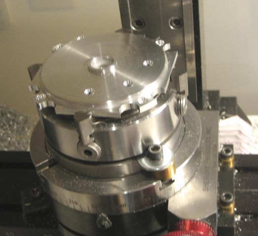
The problem with this tool plate, however, is that the work covers the two screws that clamp the tool plate to the rotary table. This causes problems because it is then difficult to register the rotary table angle calibration with the existing pillar holes.

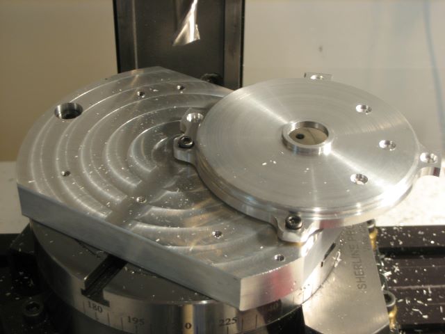
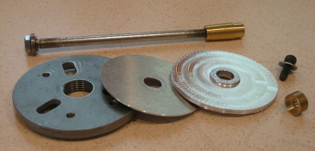
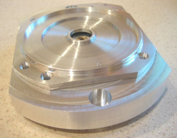
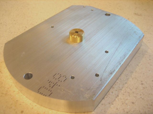
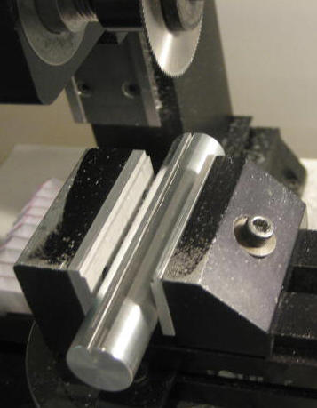
So I have made a new tool plate from 4 x 3 x 1/2 inch aluminum. This leaves space for me to tighten the clamping screws with the work already screwed down. I can get the registration that I need to continue with the profiling.

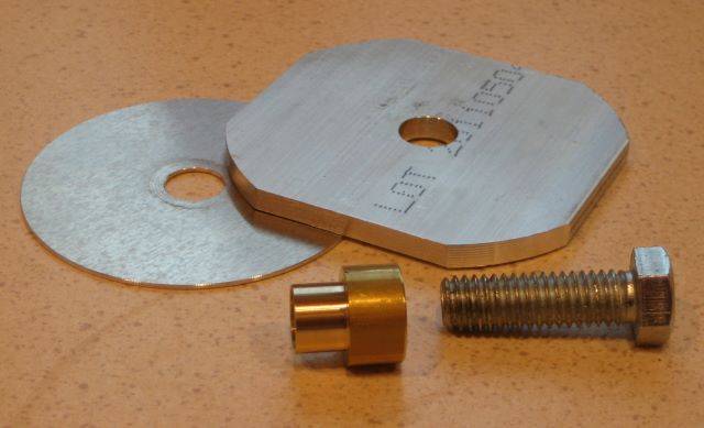
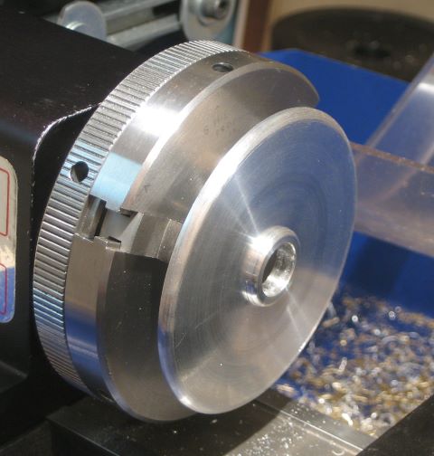
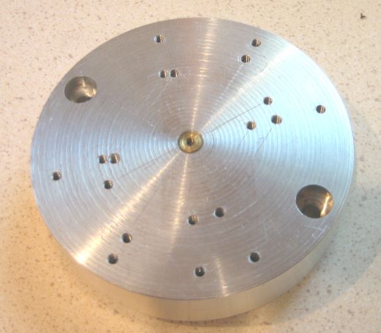
Here you see a partly made end plate on top of the new tool plate.

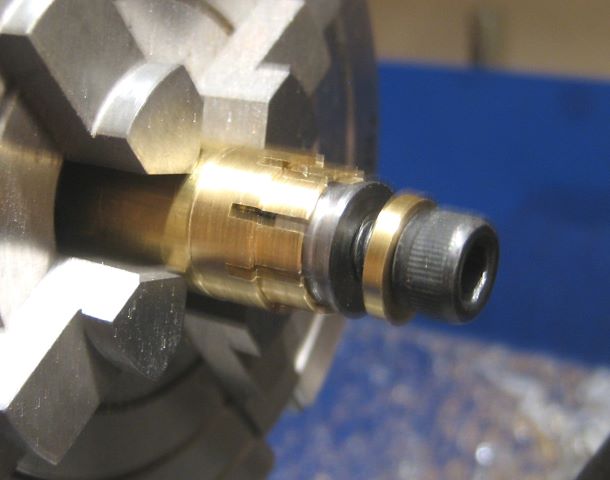
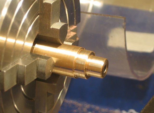
Like other tool plates that I have made for the rotary table, there is a pilot on the back.

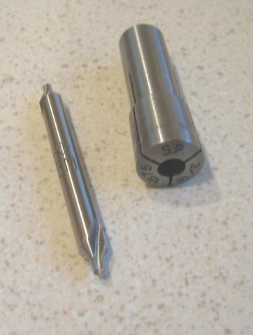
The tool plate requires many holes, accurately located. When I first started drilling this one, I followed my usual practice of holding the center drill in a Jacobs chuck. But there was a large vibration due to the inherent centering inaccuracy of such a chuck. It came as a revelation to me that center drills really should be held in collets, which are much more accurate. After all, center drills are made with shanks of standard fractional inch sizes (1/8/, 3/16, 1/4, etc) for which standard collets are available.

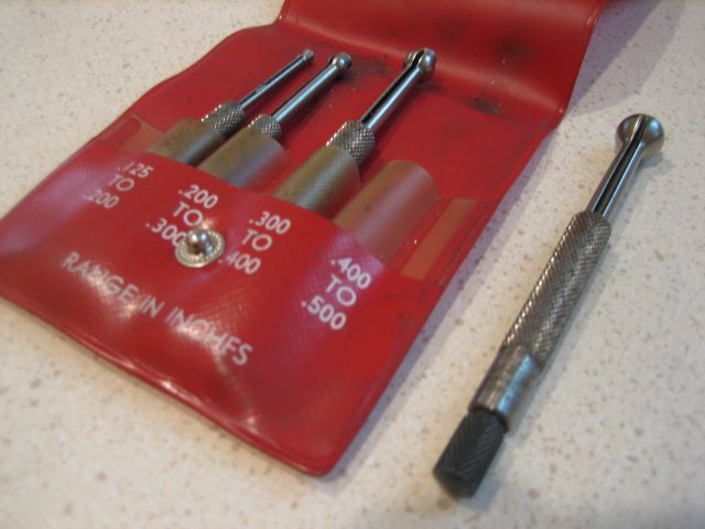
A related revelation was the reason why this set of tiny drills was made with 1/8 inch shanks; it allows them to be held in a standard collet. A tiny drill will not survive off-center driving.

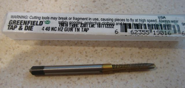
The many holes then need to be tapped. This operation goes much more quickly with a “gun tap” (a.k.a. spiral point tap) that drives chips forward instead of into the flutes. By using 1/2 inch material instead of 3/4, it was easy to through drill the plate, allowing me to use a gun tap. The many holes are 4-40.

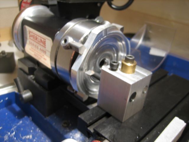
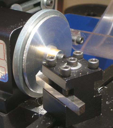
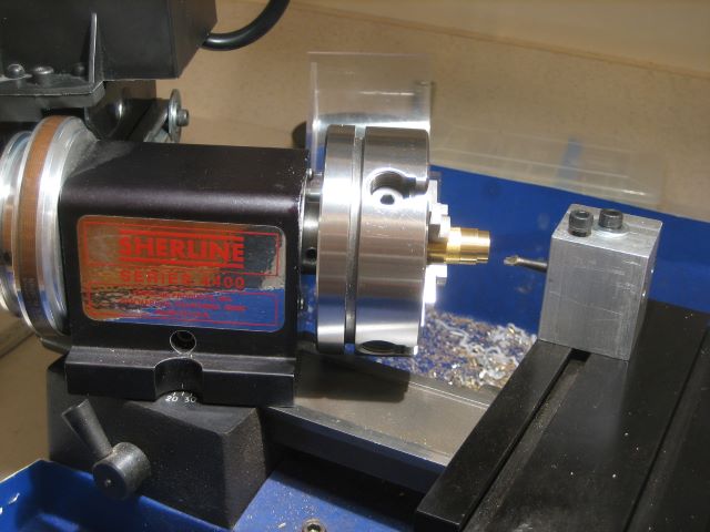
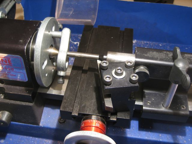
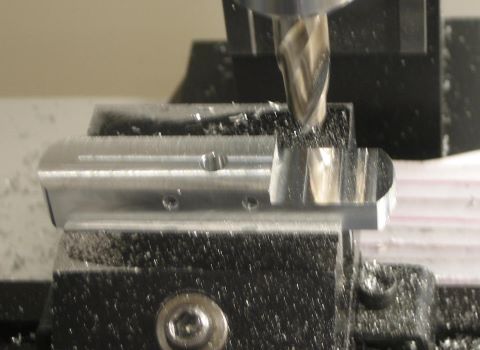
Here is a view of the tapping operation. A pin, held in a collet, pilots on the upper end of the tap wrench, thereby preventing side loads and tap breakage. In this case the collet is not needed for centering accuracy but to save vertical height. A Jacobs chuck, even 1/4 inch, would not have also fit into the limited height of this Sherline mill.

Posted in Fixtures, Work Holding | 1 Comment

Sole of the Foot

The AFFTA standard for fly reel feet calls for a 0.350 radius on the bottom. It seems strange that they chose this decimal fraction of an inch; why not 11/32 so the radius can be cut with an 11/16 ball end mill that you can buy? Or perhaps 18 mm, which could also probably buy.

At any rate, the largest end mill shank that I can use on my Sherline mill is 3/8, so I have to rough out the sole with multiple passes of a 3/8 ball end mill, then sand. There is a geometry problem involved in figuring out how deep to make each pass.

I have both a 2 flute and a 4 flute 3/8 ball end mill, and I have just discovered which is more suitable for the hollowing task. Normally I would expect to use a 2 flute end mill on aluminum. But in this case, the four flute works better. There is a tooling hole (0.194 diameter) in the center of the foot, and the end mill has to pass over it. Here is a detail of two soles, both partly sanded.

The 2 flute cut is on the left and the 4 flute cut is on the right. In cross section, the two flute end mill has different area moment of inertia on two axes, whereas the four flute end mill is symmetric. I believe that this causes a different (and larger) vibration in the two flute tool, disfiguring the area around the hole. The damage seems to be too great to sand out. I could put off the hole drilling until after the sole has been hollowed, but this is inconvenient.

To date I have done the sanding by finger power, using a wood dowel (0.68 diameter) to back up the wet/dry sandpaper. To speed the process, I have now made an aluminum dowel that can be spun on my lathe. Here I have sawn a slot to trap the ends of the sandpaper. There is also a shallow flat centered on the slot.

Here is the dowel mounted on the lathe. The sandpaper is secured with rubber cement.

Posted in Abrading, Foot | 5 Comments

7075 Aluminum

The most widely available aluminum alloy for home craftsmen is 6061. I have been using 6061 for many of my reel components. But when I decided that I should make (vs. buy) aluminum screws, I chose alloy 7075 to get higher strength. While making screws, I found that 7075 machines as easily as 6061, despite its greater strength and hardness.

Later, I notice a small problem with a reel that I had made. I had it mounted on a bamboo rod with “Leonard style” hardware, wherein a nickel silver ring slides back over the front part of the foot. The ring made a small scar on the softer 6061 aluminum foot. This would not have happened with a locking style of hardware, which I prefer in any case. But I decided to try 7075 for the feet of my next batch of reels.


And the machining is going quite well. I would say that it is definitely better than using 6061. When I mill 6061, small chips get welded back on to the finish surface of the part. This is not happening with 7075.

Comparison of the two alloys (data from On-Line Metals):
6061: 40 ksi yield, 45 ksi ultimate, 60 HRB
7075: 73 ksi yield, 83 ksi ultimate, 87 HRB

The aluminum guide of McMaster-Carr rates 6061 machinability as “fair” and 7075 as “good”.

Like 6061, 7075 can be anodized without “smutting” problems.

The disadvantages are
1. Higher cost – not a big factor for the small cross sections needed for screws and feet.
2. Lesser selection of bar size. To make a foot of 6061, I can buy 3/8 by 5/8 rectangle and mill to 0.550 width. When using 7075, I have to buy 1/2 by 3/4 and mill to 0.37 by 0.550.

Posted in Foot, Materials | Leave a comment