Progress Report #4

I have a substantial part of the machining done on two reels that I expect to deliver at the end of January.

The spool ends here have been tumbled and will brighten up with fine sanding. The end plates are straight off the mill and need coarse sanding, then tumbling and fine sanding.

I have occasional casualities when doing this work. Here is a front end plate that I destroyed late in the process. A momentary confusion of the Y and rotary axis handwheels made the lug lopsided. A day’s work ruined in a instant.

Posted in My Reels | Leave a comment

Plans for Aluminum Frame Reel

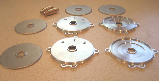
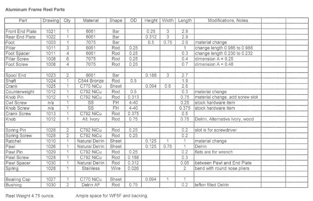
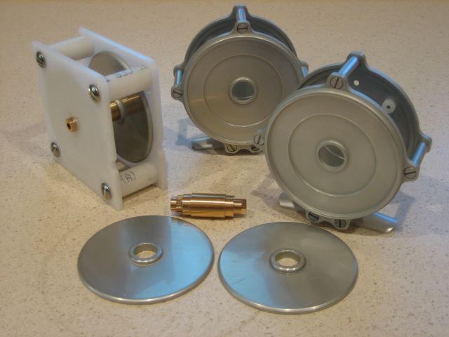
I have been machining parts for the Aluminum Frame Reel from a few finished drawings, but mostly from sketches on yellow lined paper. It is time to put together all the drawings, so next year I can still figure out what I did. Here is a reference table for the parts and drawings.

Construction Notes for Aluminum Frame Reel
Much supplemental information on making this reel is in my blog, http://northbranchreels.com or https://northbranchreels.wordpress.com. When a note below includes a date, look at the blog for that date. Note the “Archives” and “Categories” widgets on the right side of the blog page, they will help you find things.
Many parts for this reel are borrowed from my earlier design. The notes that follow describe any modifications to those parts. You can purchase a hard copy of the plans at The Eclectic Angler, or just view the drawings (lower resolution) on this blog (7 May 2011). Drawings 1000 through 1018 are in the old plan set and 1021 through 1030 are given here.
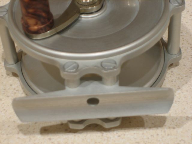
Drawing 1003, Foot
To make a stronger/harder foot, I have switched from 6061 to 7075 aluminum (21 Sep 2011). Drawing 1003 lacks the overall length of the foot, which is 2.50 inches per the AFFTA reel foot standard. Also see 25 Sep 2011, 28 May 2011, 28 Sep 2010.

Drawing 1008, Screws
Shorten 6 pillar screws from 0.30 to 0.25, and 4 foot screws from 0.53 to 0.48. See 18 Nov 2011 on threading with a die.

Drawing 1010, Ratchet
Change material from bronze to Delrin or Acetal Copolymer. I have switched involute cutters from #4 to #8 to get a rounder tooth, but this is not very important. This is a ratchet and not a gear so profile is not critical. Grinding your own “one tooth” cutter would be a reasonable approach. 10 May 2010.

Drawing 1011, Pillar & Foot Spacer
Increase pillar length from 0.985 to 0.988, and spacer length from 0.230 to 0.232. This is more of an accounting issue than a significant dimensional change.

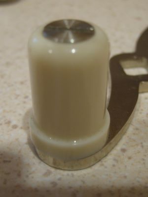
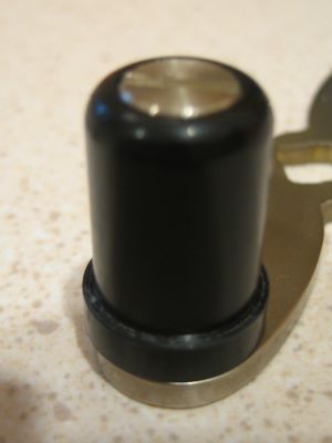
Drawing 1012, Crank Parts
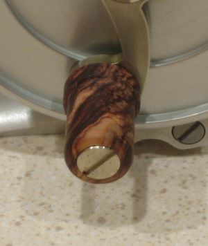
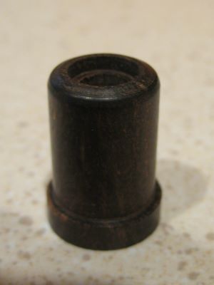
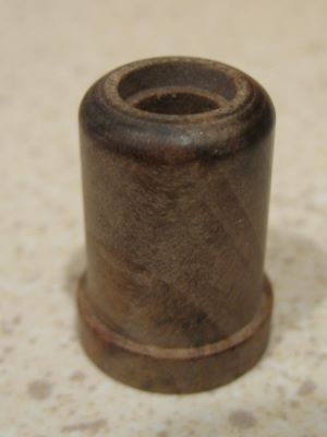
Change Counterweight and Knob Pin from aluminum to nickel silver. Add a screw slot to the pin, 0.040 wide by 0.035 deep. Knob could be made from Alternative Ivory or wood.
When the counterweight was made from aluminum, it did not balance the knob and aluminum knob pin, but the parts were light enough that there was no problem. When the counterweight and knob pin are made from nickel silver (as here) there is a good balance. (13 Dec 2011, 18 Jul 2011, 15 Oct 2010).

New Drawing 1021, Front End Plate
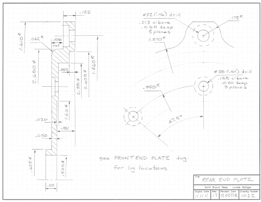
New Drawing 1022, Rear End Plate

See blog 2 Nov 2011 and 12 Nov 2011. Set angles carefully and use rotary axis lock on table.

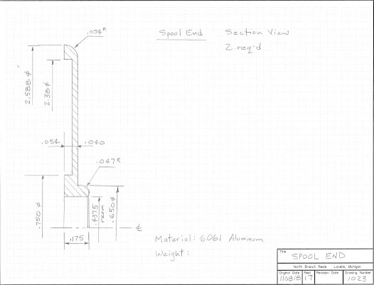
New Drawing 1023, Spool End
See blog 17 Oct 2011 for fixtures.

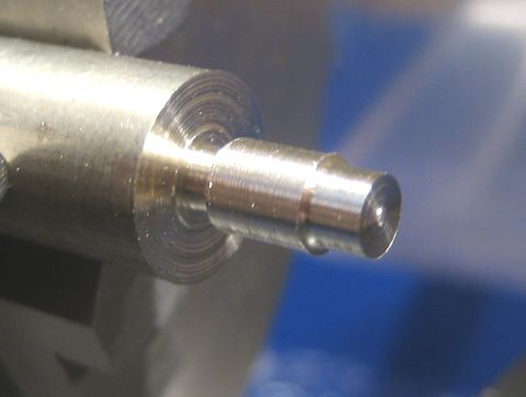
New Drawing 1024, Shaft
Drill and bore 2 parts, join, then machine outside diameters (13 Oct 2011). The drawing shows that the two parts are to be brazed together, but I now think that it is better to bond them with Loctite 609 (23 June 2011).

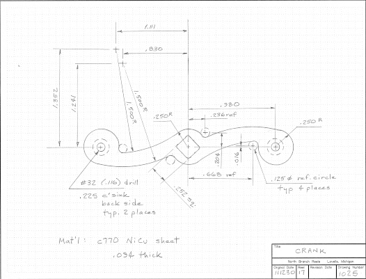
New Drawing 1025, Crank
You will need a tool plate similar to Drawing 1014 (4 Oct 2010). But the arc centers here are different, so the tool plate holes have new locations per the new drawing.
If you wish to be correct according to EVH, you will learn that this crank is RHW, and should be turned over (i.e., countersink other side) for LHW.

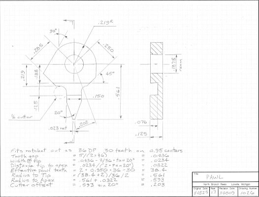
New Drawing 1026, Pawl
Delrin or Acetal Copolymer (11 Apr 2011). I make this by first drilling the hole, then screwing the blank to a post on the rotary table. After that, just make passes on the mill.
Pawl as drawn is for left hand wind. For RHW, either make an opposite hand pawl, or just turn it over in the assembly.

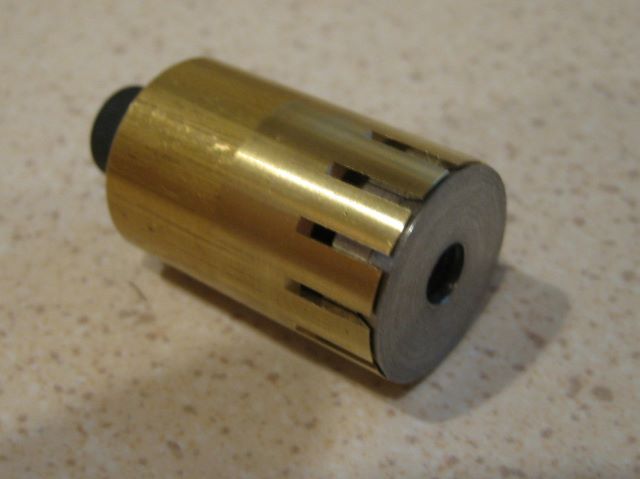
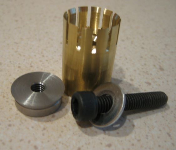
New Drawing 1027, Bearing Cap
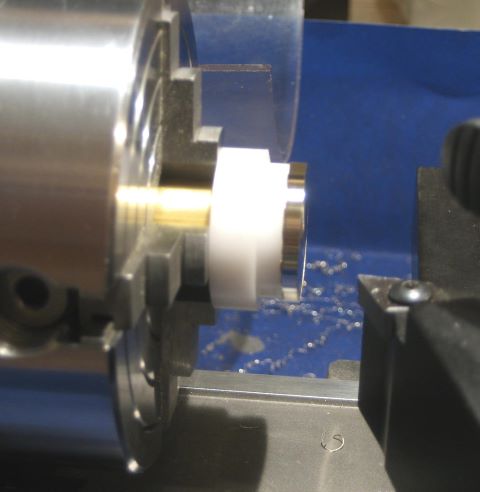
A place to engrave your logo, or a serial number. See 6 Dec 2011 for mandrel. Make the concave arc with a round file. Attach to Rear End Plate with Loctite 609 (and 7649 Activator on the anodized aluminum).

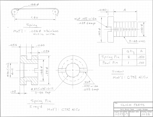
New Drawing 1028, Click Parts
View assembly 17 Dec 2011. Run screws into threading die as far as they will go (18 Nov 2011).

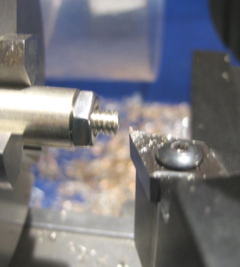
New Drawing 1029, Pawl Pin
Flats are for wrench. #38 drill hole is for clearance of partly formed screw thread.

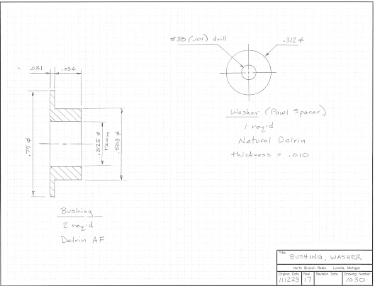
New Drawing 1030, Bushing & Washer
Delrin AF is a teflon filled material. I ream the bore, but end up with a hole smaller than 5/16. That is why the shaft journals are just 0.309 diameter.
Washer is held between Rear End Plate and Pawl Pin, it centers the pawl on the ratchet.
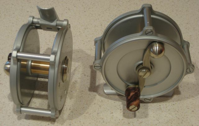
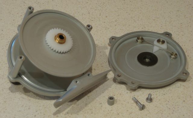
Spool Assembly
See blog 27 Aug 2010 and 23 Nov 2011 regarding bonding with Loctite 609.
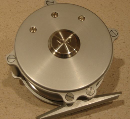
Overall Assembly
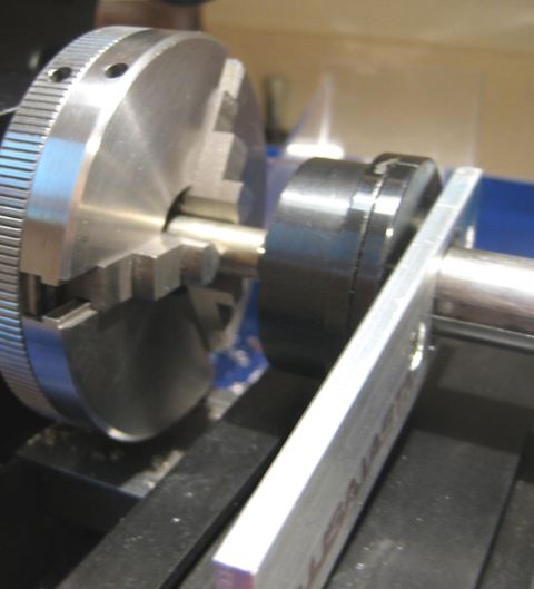
Threads can be locked with medium strength Loctite or Permatex. But the spool of this reel can only be removed by disassembly, so plan on having to extract a tippet from the bowels and omit Loctite from 5 frame screws on the Rear End Plate.
My drawings do not have tolerances on the dimensions; all parts fit “line to line” as dimensioned (hence the tiny length adjustments on drawing 1011). The first time that you screw everything together, the spool will probably be locked up in compression between the bushings. Shave the bushing flanges to get a little clearance. You can hold the End Plate/Bushing assembly in a 3 jaw chuck while doing this on a lathe.

Posted in My Reels, Plans | 7 Comments

Toolmaker’s Clamps

A friend gave me this pair of clamps. They were made by Brown & Sharpe, perhaps 1950s or so, and have the part number 754-A-5/8. I believe the 5/8 in the part number indicates 5/8 inch jaw depth.

The bars here are of 5/16 square section and the threads are 6-32. Brown & Sharpe still offers such clamps (see Amazon) but nothing as small as these. McMaster-Carr has some similar clamps with jaw depth as small as 3/4 inch. Also known as “parallel clamps” or “parallel bar clamps”.

Posted in Tools, Work Holding | Leave a comment

Progress Report #3

Two reels finished and ready to ship.

Reels 17 and 18.
Here is the final configuration of the click.

And a meager assortment of parts for the next two.

Posted in My Reels | 1 Comment

Sherlock Holmes, Metallurgist

Recently I anodized two reels. All end plates and pillars (6061 aluminum) look right. The feet (7075 aluminum) look right. Of the 20 screws (all 7075 aluminum), 14 look right but 6 of them are dark and dingy. What happened? Each reel frame was anodized as an assembly, so the dark screws did not get a different process

I had to put this aside and work on other parts while I thought about it. After a few days, I had a theory. I had bought 10 rods (0.25 inch diameter) of 7075 to make screws. By the time I did these reels, I was on the 4th rod and had had no problems. Part way through making these 20 screws, I started on rod 5. Was this rod really 7075, or perhaps something that does not anodize well, like 2024?

So I made small anodizing samples from each of the 5 rods yet unused. I also made a sample from a 6061 rod, and one from the partially used rod (#5) that may have been the source of the 6 bad screws. I marked the samples with a file so I could match them to the rods.

And when done anodizing the samples, I had 2 that were dark and 5 that were correct. The two dark ones were from rod #5 and from one of the 5 unused rods.

So now I knew which rods I could use to make replacement screws. The new screws all have proper appearance after anodizing.

My conclusion is the the vendor sent me 8 rods of 7075 and 2 of something else.

Update 12 Sept 2012: Further tests on the unknown material posted 5 Sept 2012.

Posted in Anodizing/Plating, Materials | 5 Comments

Knobs

I am getting down to the final details on the first two reels of my winter 2011-12 production. This week I am making knobs of a variety of materials.

This is “Alternative Ivory”, a plastic substitute for the real thing.

Plain black Acetal also shines up well when sanded with Micromesh pads.

I also purchased several “stabilized” blanks meant for pen making. (Correction, 15 Dec.: These woods are not stabilized. I had looked for stabilized wood but did not find what I wanted.) I was able to machine these with the same HSS tools that I would use on plastic. This is rosewood.

Here is another rosewood from the same block.

South African Ebony

Black and White Ebony

Walnut

The woods do not seem to respond to sanding with grits finer than 600.

Posted in Knob, Materials | 1 Comment

Second Expanding Mandrel

When I prototyped my aluminum frame reel (blog post of 10 Aug 2011), I fastened the rear bearing cap with two small screws. For the “production” reels, I did not want protruding screw heads, and so decided to secure the cap with Loctite 609 retainer. This allowed me to make the cap smaller. In this photo, the original cap is at the upper left.

The cap is a simple part and has only a recess on its back side to hold it by when machining. With a smaller cap, I can no longer fit the jaws of my 3 jaw chuck into the recess. So I have made another expanding mandrel, quite like the one posted 16 October 2011.

Because this mandrel fits into a blind recess, the tightening bolt comes in from the rear. When the mandrel is held in a chuck, I can still access the bolt through the hole in the center of the chuck.

Like the earlier mandrel, the fingers are about 0.06 inch wide, 0.03 thick, and 0.25 long. The taper angle for the plug is again 25 degrees. The strength of the grip is satisfactory for machining the rather hard 18% nickel silver.

The first mandrel was not successful because I was holding a 2.6 inch diameter spool end by its 7/16 diameter bore. It was difficult to get the part on the mandrel straight, and there would be excessive axial runout at the rim of the spool end. Here I am holding a 7/8 diameter part by a 5/8 diameter recess, so it is less of a problem to get the part on straight. Nonetheless, I could still detect some axial runout. So I made a Delrin spacer to fit over the mandrel and ensure that the part is on straight. I could perhaps have done this with the first mandrel also, had I thought of it.

Posted in Bearing Cap, Fixtures, Work Holding | Leave a comment

Pflueger Hawkeye

This is another one of Steve’s reels. It has rubber sideplates and nickel silver rings. It is small, only 2.5 inch ring diameter and 0.88 between rings. He has it fitted with a WF3F but no backing, and says that it will not carry a DT3F.


It weighs 5.25 oz without line. Spool capacity is about 1.8 cubic inch. Notice that the spring is a round wire that has been ground flat at the ends. The click is loud and crisp.

From the Classic Reels forum, I learned that Pflueger made the Hawkeye in 40, 60, 80, and 100 yard sizes. This one is evidently 60 yard. The 40 yard model has rings of 2.12 diameter.

Posted in Classic Reels | 3 Comments

Bonding Fixture


The Delrin assembly on the left is a fixture that holds the spool ends square on the shaft while Loctite 609 adhesive sets up. The ends fit a bit loose (0.001-0.002) on the shaft because there has to be some room for the adhesive. That is loose enough that a spool end can go on crooked. I made this fixture to (hopefully) avoid having to re-do any of the bonds.
Frames and end plates have been anodized.

Posted in Bonding, Fixtures, Spool | Leave a comment

Starting a Threading Die

I am finishing end plates, and that involves a lot of tedious hand work and a lot of waiting for the tumbler to do its job. There is a feeling that no progress is being made. So as a remedy, I am making the crank screws. At least something seems to be getting done.

Small screws (this one is 8-32) are most quickly cut with a threading die. The problem is starting the die; it is likely to chew up the end of the screw before biting in and cutting. So my foolproof scheme is to make a blank longer than is needed, and then turn a small diameter at the end. Here is a screw blank properly prepared.

The depth of a 32/inch thread is about 0.027 inch, and the reduced diameter here is about 0.027 less than the full diameter of 0.164. It is applied to the last 0.100 of the screw, enough length for 3 threads. You can see a “neck” behind the area to be threaded; it has nothing to do with starting the thread.

The threading die readily engages the reduced diameter at the end. And by the time it reaches the full diameter, it is gripping the blank very well.

So all I have to do is turn the crank, no fiddling to get the die started.

Next I screw on a steel nut.

Then trim to length (i.e., remove the reduced diameter section).

And file a little to remove burrs.

Remove the nut (properly forming the end of the screw) and there is the completed thread.

Now it is time to part off.

To work on the heads, I put the screws on a brass mandrel.

Update 15 Nov 2012: I am beginning to realize that the quality of the threading die is a factor. Several of the dies that I have will climb right up onto a full diameter, without any lead-in diameter as I described here. This saves a lot of time when making several screws; you don’t have to go back and trim the end. When I originally wrote this post, I was using a die that may not have been shaped well.

Posted in Cutting, Screw | 6 Comments