Bougle

Alan is a member of my Select Advisory Panel on Reel Aesthetics, and he owns this Bougle.

It is not an antique, but it is certainly a classic.

Legends engraved on the winding plate are:
* Made in England by Hardy
* “Bougle” Centenary
* 3″ lightweight
* Mk V

From the website of a wiley dealer who stocked up on these, I find the following descriptions.
* Model 3″
* Diameter 3″
* Weight 3.7 oz./105 g
* Line Capacity (m) DT2+70m/WF3+50m
* polished racing green anodized frame
* satin gold anodized winding plate and spool
* hard anodized aluminum spindle for further weight reduction

Alan insists that the spool color is “champagne”. My photos do not reproduce the color very well. He has loaded the spool with a DT4 and 10 yards of backing; I would say that it is not overloaded.

I measure it as 4.0 oz w/o line, 2.75″ diameter (3.06″ over pillars), 1.35″ width.
Spool Volume = 3.1 in^3.

Here are a couple photos of the innards:

Posted in Classic Reels | 1 Comment

Brown Drake Spinner

The premier insect event on the North Branch of the Ausable is Brown Drake emergence and (3 days later) spinner fall. This year I have arrived at a satisfactory spinner pattern.

Hook: 2X long #12 or #10 (Mustad 94831 or Daiichi 1280)
Thread: 6/0 olive or tan
Tail: moose body
Abdomen: deer hair (short, coarse)
Wings: saddle hackle

The tails and body are like Roberts Drake. I use moose for the tail because pheasant tail barbs stick together and always look like one fiber.
Deer hair is hollow so this fly floats without a lot of fussing with floatant. Dubbed bodies always get waterlogged.

The wings are a “widespread fiber spinner wing” from a book by Vince Marinaro. For these, you wrap a saddle hackle (less the fuzzy lower part) around the hook, then force the fibers to the desired position with figure 8 thread wraps.

Marinaro made a “slant tank” to observe the appearance of real flies and of imitations from below the surface. He concluded that this was the most realistic wing.

Ephemera simulans is a burrower that lives as a nymph in the silty margins of the stream. Why we have it but not Hexagenia limbata, I cannot explain.

Update 6 June 2014 : I am reading Hatch Guide for Upper Midwest Streams by Ann R. Miller. In her discussion of the Brown Drake Nymph, she says “Search out their habitat of sandy-gravel stream bottom – not silt!“. So that is the reason we have Brown Drakes but no Hex – the North Branch does not have enough silt.

Posted in Bugs | 4 Comments

Dyed End Plates

Having dyed some scrap metal parts (this blog, 23 April 2012), I moved on to some machined reel parts. On my first attempt, the result was not satisfactory. There were small but obvious flaws, like this spot on the rear end plate.

And this one on the front end plate.

I had taken the usual steps for anodizing: wash in dish detergent, wash with degreaser, handle with finger cots (but just 2 on each hand). My dyeing vessel was a mini crockpot that was not large enough to suspend the end plates vertically. So I attached “legs” made of screws and spacers at 4 lugs . These held the part up off the bottom of the vessel, but oriented horizontally. I now think that attaching the legs was too much handling, and some of the dye smudges are prints from fingers without cots.

So I stripped off the unsatisfactory coating with caustic soda (lye) and made another try. This time I was prepared with some wire hooks so that I did not have to handle the parts, either from wash to anodize or from anodize to dye.

The more complex wire part is a rack that holds an end plate horizontally in the dye.

I also soaked the parts in a hotter detergent solution for a longer time. The caustic soda etch (to remove the first anodize layer) may also have help make a cleaner part.

On the second attempt, the parts were without noticeable flaws on the surfaces that are visible on an assembled reel.

I did manage to trap an air bubble underneath the front end plate, so there is a patch that is anodized but not dyed.

Here are a couple pictures of the finished reel, number 24.


I believe this will be the end of my “aluminum frame reels”. It is spring and time to fish. For next winter, perhaps a new reel design with fixed spindle.

Posted in Anodizing/Plating, End Plate, My Reels | 3 Comments

The Last Word on Alignment

I am a great admirer of Starrett “Last Word” indicators. My collection is now quantity 4. These are lever type (as opposed to plunger type) indicators that look like they were designed in 1914. The range of measurement is only about 0.030 inch, but I find them to be very handy for alignment. The dial marks correspond to 0.001 inch, but are far enough apart that you can judge alignment to about 0.0002 inch.

Here is a 711F (top) and a 711C. The F is more versatile, having a lever on the side that reverses the direction of the tip and a threaded hole at the top of the body for attaching a stem (shown).

The indicators are very rugged and last forever, so there are normally a lot of them on Ebay. I have typically paid about $20 for a basic indicator. You also will see boxed sets with accessories (two typical accessories below) and these sell for more. My advice is to skip the accessories; I do not find them to be very useful. The accessories that I am constantly using are ones that I have made.

One difference among the indicators is the diameter of the ball at the tip. Here you see that the tip can easily be replaced by moving a spring clip.

Radial serrations connect the tip to an internal lever, and allow quick adjustment of tip angle.

Long Island Indicator has spare parts and offers a fixed charge to repair these indicators. They also give instructions on doing repairs yourself.

Here I am holding an indicator by its stem in order to check that a vise-held block (the blank for a reel foot) is perpendicular to the mill spindle.

I make reel end plates by alternating mill and lathe operations, holding the material in a 4 jaw chuck. Both sides have to be machined, so I have to rechuck when I turn the part over. The indicator guides me to recenter the part.

Most often I center on an outside diameter, but here you see that it can also be done on an inner diameter.
The indicator is mounted on a homemade base made of aluminum, 1144 rod, and a swivel joint from McMaster. It is similar to the usual magnetic base for indicators, but the cross slide of a Sherline lathe is made of aluminum.

Here is a simple homemade accessory (two pieces of 1144 rod) that I use to center the mill spindle over a rotary table. The indicator dial faces away from me when I rotate around to the back side, so I keep a small mirror handy.

Posted in Alignment | Leave a comment

43 Parts

Here are 43 parts that will become reel #23.

Just finished sealing the anodization on the aluminum parts.

Update 1 May 2012: Here it is all screwed and glued.

Posted in My Reels | 1 Comment

Anodize Dye Samples

I finally got around to trying some anodize dyes. Dyeing is an extra step in between anodizing and sealing.
First, I did a normal anodization to obtain a 0.001 inch thick coating. Conditions to achieve this are discussed in the March 3, 2012 posting to this blog.

I did my dyeing of these small samples in a 16 ounce mini crockpot, using 8 ounces of diluted dye. This crockpot did not have a power control, so I ran it with a variac in order to maintain the solution at 140F.

The dye solution is 8 ounces of distilled water and 1/8 ounce (3.7 ml) of dye concentrate. To measure the dye concentrate with some accuracy, I used a transfer pipette. It is graduated, and can pick up 1 ml at a time.

Sealing is the usual procedure of boiling in distilled water. I did not observe dye leaching into the sealing water.

Across the bottom of this picture are 4 dyed samples: Black HBL, Bronze, Copper BF, and Gold S. These are from Caswell. Also in the picture for comparison are two scrap pieces of 360 brass.

The Gold dye comes out the closest to brass, but my samples were unevenly colored.
The Copper dye is something of a strange color, best described as “pumpkin”.
The Bronze dye is quite dark, like a piece of sculpture that has been given a patina.
The Black sample is quite satisfactory. This dye is more expensive than the others.

To get a satisfactory brass color, I will try to mix some of the dyes. I intend to use such a mixture in order to make “bimetal” reels.

Posted in Anodizing/Plating | 1 Comment

Ratchet Teeth

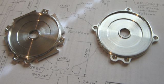
When I made my first reel design, I had to find a way to make a serviceable ratchet. First there was the problem of what material to use; this blog has several post on material testing. But there was also the problem of cutting the teeth of what looked a lot like a gear.

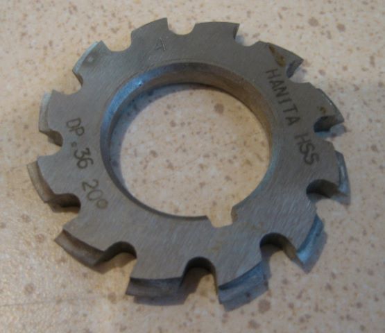
Wholesale Tool then had some close-out specials on “Involute Gear Cutters”, and I bought several of these that were for 36 diametral pitch, 20 degree pressure angle gears. This is the type of cutter that comes in a set of 8 to cut gears of the full range of tooth numbers.

My ratchet was to have 30 teeth, so at first I used the #4 cutter, correct for gears of 26 to 34 teeth. Later, when I realized that involute profile is not important for a ratchet, I started using the #8 cutter, designed for 12 and 13 tooth pinions. This cutter rounds off the tooth tip a little better. In ratchet-pawl operation, the flank of the pawl repeatedly impacts the corners of ratchet teeth, so round tooth corners reduce the impact stresses. This is different from gear action, where involute profiles mesh.

(Aside: As I understand the 8 cutter system, the #4 cutter is correct for 26 teeth, and has “acceptable error” for 27 to 34 teeth. This point is relevant to gear cutting but not to ratchet cutting.)

Update 24 June 2013: I have stopped using the #8 cutter when making ratchets of 20 to 30 teeth.
When indexed at smaller angles than 360/13 = 28 degrees, the two involute profiles on the sides of a tooth actually meet at a diameter less than the ratchet OD that is desired. I am now using whatever cutter is appropriate for the actual number of teeth in the ratchet.

I chose to buy 20 degree pressure angle cutters instead of 14.5 degree for two reasons. First, it was the 20 degree cutters that were on close-out sale. Second, the 20 degree profile is a little rounder than the 14.5 degree profile because 20 degree is generated from a smaller base circle.

Once I had a working prototype reel, I made a complete drawing set. This set can be purchased at The Eclectic Angler.

Anyone trying to follow these plans has a bit of a problem when it comes to the ratchet, however. I did not know it at the time, but English cutters (based on diametral pitch) are almost always 14.5 degree pressure angle, and metric cutters (based on module) are almost always 20 degree pressure angle. The cutters that I got from Wholesale Tool were an oddity. Nowhere on the Internet can I now find 36 DP, 20 degree cutters.

In case anyone is stymied by this problem, I offer the following several solutions.

1. Buy a gear
SDP/SI has acetal gears based on diametral pitch but with 20 degree pressure angle. The closest diametral pitch is 32. Choose a 26 tooth gear and the pitch diameter is then 0.8125 inch, a little less than the 0.8333 in my design. So the center distance of pawl to ratchet must be reduced by about 0.010 inch. Also, the pawl tip can be 0.005 wider because the space between teeth is 0.0491 (vs. 0.0436 in my design).
These gears need modification: cut out the hub and reduce the face width.

2. Cut a gear with a 14.5 degree cutter
In this case, the total included angle at the pawl tip should be 29 degrees instead of 40 degrees. If you do not change the pawl, you may find that the pawl jams between gear teeth when spool direction is reversed.

3. Cut a gear with a module cutter
You can find 0.7 module (metric) cutters of 20 degree pressure angle from several sources. This is a diametral pitch of 36.28 per inch diameter. A 30 tooth gear has a pitch diameter of 0.8268 inch, or 0.0066 less than the 36 pitch gear in my design. Compensate by reducing center distance from ratchet to pawl by 0.003 inch.

4. Use a 60 degree V groove cutter.
You will want a 60 degree angle at the tip of the pawl also. Be sure to adjust pawl length so the ratchet-pawl set can pass “over center” when spool direction reverses. The tooth tip corner will be quite sharp, so it would be a good idea to round it off a bit. Perhaps a second pass with a 90 degree V groove cutter would work.

5. Grind a single tooth cutter
Sherline sells a one tooth gear cutter (P/N 3217), for which you grind the end of an HSS tool blank to the shape of the space between two teeth. This is a good approach; you do not need an accurate involute to make a ratchet, and you can round the tooth tip as much as you want.

6. Machine a single tooth gear cutter, then harden it
There is a YouTube showing this process. The involute profile is approximated by a circular arc.

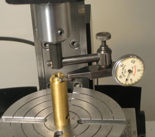
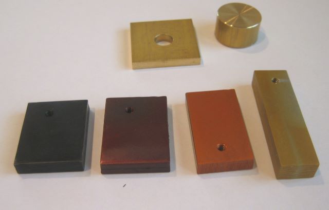
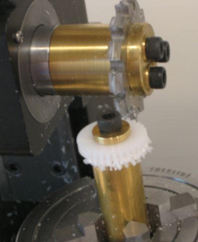
Here I am cutting teeth on an acetal (Delrin) blank. I am convinced that a plastic ratchet is superior to a metal ratchet because a properly chosen plastic is tough whereas metal is brittle. The toughness causes a small problem when cutting teeth: a shaggy looking gear when you are done. It takes more time to clean up the teeth than to cut them.

Update 16 Jan 2013: Finally found a source for DP sized gear cutters with 20 degree pressure angle, http://mdmetric.com/prod/meda/medatoolsupply/columnar4950.html?cat_id=9608&&category_site=MEDATOOL
Update 22 Nov 2014: Here is an updated link

Click to access 2_chapter-pages.pdf

See page 152 for 20 degree pressure angle cutters based on diametral pitch.

Update 26 Oct 2017: I have recently tried to order from mdmetric.com and find that they are totally unresponsive. Apparently they carry no stock but instead make a custom order to some supplier of theirs for tooling. But here is another source that appears to carry stock: KBC Tools .

Posted in Milling, Ratchet/Gear | 2 Comments

Digital Micrometer

I recently bought this micrometer from Anytime Tools. It is a standard micrometer with a vernier scale on the handle that allow interpolation to 0.0001 inch. What is different is that there is also a revolution counter that shows the reading to 0.001 inch. Its country of original is not obvious.

My engineering education is from the time of the slide rule, so it doesn’t bother me to read numbers from “analog” scales. But I compromised with the modern world, and my Pickett N3-ES now stays in the desk drawer while I use an electronic calculator.
For readings to 0.001″, this micrometer agrees with my old Mitutoyo. So I converted quickly; this is the micrometer that I habitually pick up. It is quicker and more certain than reading the engraved scales.

Posted in Measuring, Tools | 2 Comments

Abrasive Grits

A recent discussion at Reelsmithing caused me to think about the size of abrasive grits and the roughness of the surface that they would produce. My intuition was that an abrasive particle of 0.001 inch diameter might produce a surface roughness of 0.0005 inch or so. But there seemed to be a mismatch between the commonly available grits and the roughness (Ra) typically produced; i.e., the reported roughness is much less than than 0.5 * grain size.

So I googled around and found a chart that answered this question. It comes from Pace Technologies, a purveyor of supplies for the metallograph business. Clearly people who know their grits. The first four columns in the chart below are their data.

I added the last three columns. Columns 5 and 6 just convert their data to English (note micron = micrometer and mil = 1/1000 of an inch). Column 7 gets at the heart of the matter. It is just the ratio of the data in the previous two columns, and it shows that for a given abrasive particle size, you can get a surface finish with Ra of about 1/200 the particle diameter. So now I better understand what grit to consider.

This data is for finishing hard steel and it probably makes some difference if you are working with softer metals, but I have not yet discovered this piece of the puzzle.

In the Reelsmithing discussion, I steered the attention away from Brent’s very sophisticated reel and toward my own topic of interest. I apologize to Brent for this. When I get the chance to quiz a guy who knows more than me, I cannot resist.

Update 19 Dec 2014: I was trying to figure out sharpening stones, which are usually described as “fine, medium, coarse”. Here is a chart that I copied from the catalog of Woodcraft Supply LLC.

Update 19 Oct 2015: Today I found a stupid mistake in the spreadsheet, and so have replaced it with a new one.
If you try to read the conversation in Reelsmithing, it will not make sense because Brent’s comments have disappeared.
The wikipedia article “Surface finish” has good info on what surface roughness can be obtained with what process.

Posted in Abrading | Leave a comment

Progress Report #8 : Little Progress

This is how far I got on the next two reels before I was rudely interrupted:

Last Wednesday I set these front end plates down and left the house for an evening meeting. Just before walking out, I took the first pill of an antibiotic prescription that I was given earlier in the day. While driving, I realized that I was having an allergic reaction. Systems seemed to be shutting down, so I pulled into a parking lot. Apparently I tried to get out of the truck but passed out and struck my head on the asphalt.

What I learned about hospitals is that once you are admitted with head injury, they are reluctant to let you go. They have many tests that help them to decide if you can be allowed to mingle with the general population again.

I think that the best test will be milling the two rear end plates without mistakes.

Posted in End Plate, My Reels | 3 Comments