43 Parts

My current design, the “Fixed Spindle Reel”, is comprised of 43 parts, as shown here.

If I had the machining horsepower to make a one piece frame and a one piece spool, I could reduce the part count to 25.

Posted in My Reels | Leave a comment

Snap-In Puller

My friend Jerry needed to remove a cylindrical clutch assembly that had been pressed into a recess. The only feature available for grip was the bore of the clutch. He made this puller and was able to extract the clutch.

OLYMPUS DIGITAL CAMERA


(photo by J.Drake, used with permission)
The working end of the machined part is three spring fingers that fit the clutch bore. The new idea here (to me) was making the puller a tube so that a drill rod could be pushed in to lock the fingers.
You can see many more details of the puller here.

Posted in Repair | Leave a comment

Making a Washer Flat

At the base of the spindle, my reels have a thrust washer. It is meant to take any axial forces generated during cranking.

If this washer is thicker on one side than on the other, the spindle will not sit square with the frame, possibly leading to a rub.

I make the washer from phosphor bronze rod. Working with sheet material would be quite a different process.

With the raw material chucked, the O.D. and the working face can be turned. This is the time to finely sand the working face.

Then the thin disk can be parted off. Torque is limited on a Sherline lathe, so the parting tool is only 0.040 inch thick. It wavers around during parting, so the back side of the washer is uneven.

I put the washer in a pot chuck to ream the bore.

If the washer were thick enough, this chucking would be a good time to turn the back side. But I need a washer that is only 0.031 inch thick. It would flex if turned, making the washer thicker in the middle than at the edges.

So I decided to sand the back side. Here is an aluminum disk with wet sandpaper glued on, and a Delrin holder for the washer. The face of the holder has a shallow recess to retain the washer.

This is the sanding setup.

Here is a partly sanded washer, showing that the thick portions of the disk are the first to be abraded.

Note 7 Jan 2020: All this is just too much work, and the result is not always what I would want. See the post of May 8, 2014, “Precision Washer”.

Posted in Abrading, Spindle, Thrust Bearing | Leave a comment

Cut-Off Saw

Most of the raw material for my reels is round or rectangular section bar stock purchased in 1 foot lengths. To size it for mill or lathe work, I need a saw. While I own a Delta bandsaw, I prefer to reserve it for woodwork.

So I bought a handheld bandsaw from Harbor Freight and mounted it to a hinged frame of plywood.

It would be better to have a metal frame, but my work is light duty and highly intermittant. Here you also see a drill press vise.

The saw is in my garage. Here it is ready to cut off an aluminum bar. The saw only runs when my hands are on it; no trigger lock, auto shut-off, or weights are required.

You can see in this photo that the saw fastens to the hinged plywood plate with two frame screws and one U-bolt.

This is a detail of the U-bolt. A jigsawed piece of word fills the irregular gap.

When trimming a short piece of stock, I put an adjustable spacer on the unloaded side of the vise.

The vise will hold a round bar if it is long enough, but usually I clamp the round bar to a grooved rectangular bar.

I can also hold short bars with my 4 jaw chuck. The chuck threads onto this fixture, which is in turn held in the vise.

Posted in Cutting, Work Holding | 2 Comments

Two Reels Ready

For a local customer, 2.75 and 2.25 inch.

Posted in My Reels | Leave a comment

Improved ER16 Collet Chuck

In two earlier blog posts (4 Jan 2013 and 6 July 2012), I have discussed ER16 collets. My concern here is holding small round parts “on center”, and for the discussion here, consider “on center” to be a TIR of 0.0002 inch or less. This is my limit of resolution when using antique “Last Word” indicators.

After some time, I found that the MT1 mount collet holder would itself run on center if I properly “clocked” it (that is, selected an optimum angular location). A gauge pin would then also run on center if I properly clocked the collet inside the holder.

I bought a second collet holder, one that installed on the spindle nose thread. But this holder by itself had a runout of 0.0055 inch, and was therefore useless. Since that time, I investigated the centering of Sherline chucks (see blog post immediately preceding this one) and found that the chuck mounting system provided accurate centering. This makes me think that the second collet holder probably had a defect in its threads that engage the spindle. The advantage of a holder like the second one (but running on center) is that long stock can be chucked through the center of the hollow spindle.

Then I found an improved solution, an ER16 collet holder with a flat back.

This is it, screwed to a homemade faceplate. The bolt joint allows a little adjustment of the holder so that it can be made to run on center.

So now I have a holder that automatically clocks itself to run on center whenever it is installed. Also, it accomodates long stock. Only 12 collets are needed to cover the range of zero to 3/8 inch diameter. I still have to mark the individual collets for optimum clocking. Of the collets that I bought as the original set, some run on center at all clockings and others have a preferred angular position, but all will run on center. I bought a second 5/16 collet (from another source) that will not run on center at any clocking; TIR varies from 0.0014 to 0.0026 inch.

So there are good and bad ER16 parts available. I wish that I knew how to tell what was good before purchase. The original collet set was from Micro-Mark. The flat back collet holder came from the Ebay store xs-tooling.

Additional note: The small TIRs reported above are for gauge pins chucked in collets whose bore is equal. What happens if the collet must be drawn down? I just chucked a 5/16 gauge pin in a collet with 11/32 bore. The best TIR that I could find (various clockings) was 0.0004 inch. This is not quite “on center” according to my definition, but still quite good.

Update 10 Feb 2013: I discovered a minor limitation of ER collets, that they cannot hold short pieces of material. I wanted to make a cylindrical spacer of 0.219 diameter and 0.231 length. I had the last 1/2 inch of 1/4 inch diameter rod left over, and figured that it would be enough (Scottish heritage). But this short piece of rod wiggled around in the ER collet. A Sherline “milling collet” has no trouble holding a part like this.
I do not consider this limitation serious; I have milling collets of 1/8, 3/16, and 1/4 inch diameter (i.e., stock rod sizes), and I can use these when working on short stock.

Update 1 July 2013: For someone who works exclusively with collets (say in making rod ferrules), Sherline offers headstocks that accept ER16 collets rather than M1. Look at the sherline.com web site, “Industrial Products Division”, “Industrial Headstocks and Spindles”.
Now reader Robert has advised me of another company that makes larger ER headstocks to fit the Sherline lathe, see http://www.sherlinecollet.com/collet%20spindles.htm.

Posted in Work Holding | Leave a comment

Chuck Centering

On a fly reel, the radial clearance between the spool ends and frame should be as small as possible. It is probably not practical that this clearance be as small as the diameter of the finest tippet that might be used, but a small clearance at least reduces the chance of tippets going where they should not.

On my current reel design, there are six parts for which concentricity of features is important in avoiding a rub of spool end on frame. So I am always concerned with maintaining concentricity while making parts.

Recently I read on a hobby machining forum a comparison of Sherline’s chuck centering system to that of another manufacturer of small lathes. The Sherline system was held to be inferior because it lacked a pilot diameter where the chuck fits on the lathe spindle. Here is what is under discussion.

The thread on the Sherline spindle is 3/4-16 UNF. When a chuck is screwed on, it stops when it comes into contact with the flat surface just behind the thread. So we depend on the thread itself to make the chuck concentric with the spindle. Apparently the other manufacturer provides a pilot diameter between the thread and the flat surface. Threads are cut with non-negligible clearance (for easy fit), so is there a flaw in the Sherline approach?

I decided to make an empirical investigation. Here I have centered a pin in my 4 jaw chuck to within 0.0001 inch. Then I removed the chuck and reinstalled it five times. Each time the runout on the pin remained at about 0.0001 inch. I am sure that the thread clearance is much greater than this.

So by this test, I find no deficiency in Sherline’s approach. My theory is that the thread acts as a taper. As long as we avoid trapping metal particles in the thread, the chuck centers as it is tightened. As a point of machine design, observe in the first photo that behind the thread and in front of the flat surface there is a short length of spindle for which the diameter is that of the thread root. This ensures that there is no incompletely formed end to the thread that might throw the chuck off center. I believe that this feature is called a spigot.

I think that any pilot diameter with a close enough fit to provide 0.0001 inch centering would be difficult to use; the chuck would consistently bind on the pilot as it was screwed on.

The Sherline 4 jaw chuck can also be used as a milling vise (see this blog, 7 Feb 2012). It mounts to the mill’s rotary table with the adapter shown here.

This adapter fastens to the rotary table with a 3/8-16 UNC thread. This interface also has a 7/16 pilot diameter, but the clearance is loose enough that installation and removal are not difficult..

When making reel end plates and spool ends, I frequently switch the chucked work from mill to lathe and back again. So TIR on the rotary table (for a chucked part that has been centered on the lathe) is of concern. Multiple installations of the chucked pin on the rotary table show a consistent TIR of 0.0014 inch.

So the centering error on the mill rotary table is about 0.0007 inch. That is OK for making reels. If I were making watches, I would be concerned.

Update 22 May 2013: I was wrong about terminology. The smaller diameter behind the threads is a relief, and more specifically a thread relief. So at the nose of the spindle we have threads, a relief, and (per Alan, below) a register.
A spigot is of course a beer or water tap. But a spigot joint is a particular type of pipe joint, and the term applies to some circular joints in machinery other than pipe joints.

Posted in Work Holding | 3 Comments

Mitutoyo Absolute

For Christmas I received a Mitutoyo “Absolute” caliper.

This is my first electronic-based measurement tool. I compared its measurements carefully with those of my old Mitutoyo dial caliper and decided that it works. What is amazing is that you do not have to set the zero point each time it is turned on. Turn it on while the jaws are open, and it will reliably indicate 0.0000 when you close the jaws. Resolution is 0.0005 inch.

You can get a brief description of how it works here, or the real nitty-gritty by reading U.S. Patent 4879508.

What is different from a mechanical caliper is the On/Off switch. I need to supress the urge to turn it off each time I use it; the continuous-use battery life is 3.5 years.

Posted in Measuring | 1 Comment

ER16 Collet Chuck

In a post of 6 July 2012 (“ER16 Collet Set”), I reported on a collet set that I had acquired. These were different than many collets familiar to machinists in that they were saw cut from both ends in such a way that they could contract about .040 inch in diameter, allowing just 10 collets to cover the range of 3/8 inch down to less than 1/32 inch. The collets need a holder of some type, and this set provided a holder that fit the MT1 tapered bore of my Sherline lathe headstock. At first glance, the set seemed work well, but later I noticed that I could not get consistent TIR. In many instances, TIR would approach .0100 inch. This in spite of many efforts to exclude stray metal particles from the mounting interfaces.

Now, I think that I am able to measure TIR. I use a Starrett “Last Word” indicator, see post of 5 May 2012. The needle swings of this indicator can be read down to .0001 or .0002 inch. When I chuck a gauge pin in a Sherline milling collet, I always get about 0.0002 inch TIR. This is what a collet should provide. When I chuck the same pin in my 3 jaw scroll chuck, the TIR is about .0030 inch, and this the same time after time. (I have so far resisted the temptation to start grinding the chuck jaws.) But with the ER16 collets and their MT1 holder, I see anywhere from .0010 to .0100 inch TIR. So I have shyed away from using the collet set, as I cannot depend on a small TIR. I speculate that the reason that the TIR is sometimes as small as .0010 is that error in the collet fit to the holder and error in the MT1 fit will sometimes cancel.

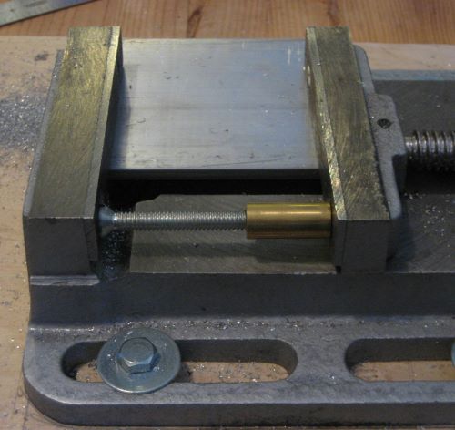
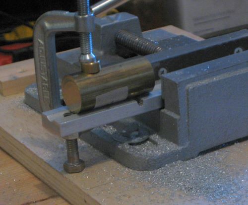
Recently I saw a different MT1 holder on offer through on-line auction. Instead of using the MT1 bore of the headstock spindle, it fits the 3/4-16 external thread at the nose. This is a big advantage in that it leaves the spindle bore open and thus allows work with longer rod stock.

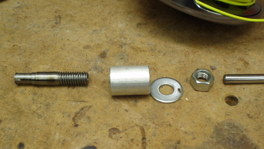
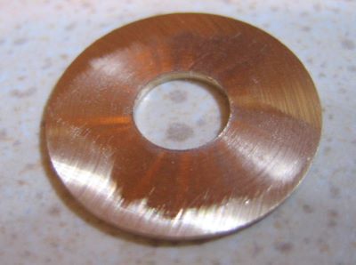
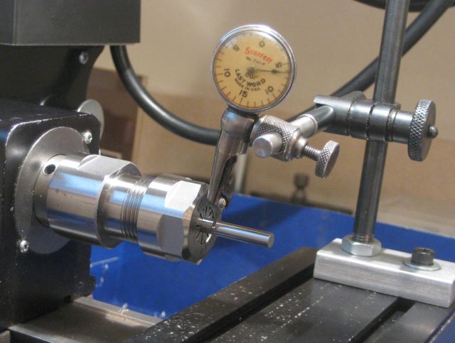
Hoping for better performance than I get with the MT1 holder, I ordered one. This is it, along with one of the collets from the original set.

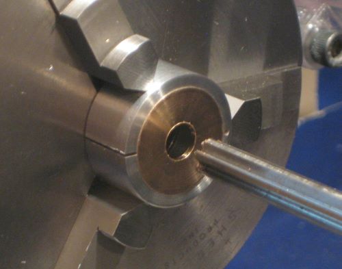
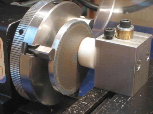
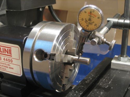
And here I am measuring the TIR on a chucked gauge pin.

It was a big disappointment. TIR was consistently in the .0080 to .0110 inch range through several disassembly/reassembly cycles.

So my conclusion is that ER16 collets provide a good grip on a cylindrical surface, but cannot be expected to give the TIR of more conventional collets.

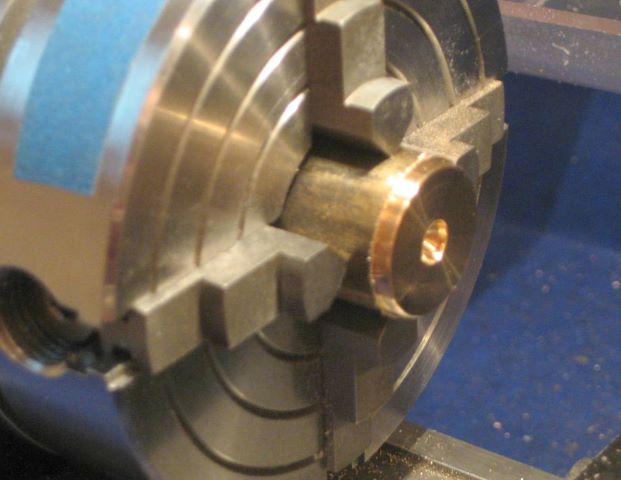
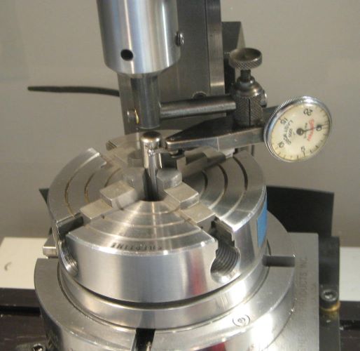
Certainly some of the fault lies in the manufacture of the collet holder. Here I am measuring .0055 inch TIR on just the tapered bore.

Sherline is able to get vanishingly small TIR on items such as their 3/8 inch end mill holder; this item should be as good.

Update 7 Jan 2013: This morning I took another look at the original MT1 collet holder. I installed it four times into the spindle, and measured TIR of 0.0005 to 0.0008 on the tapered bore. But each time when I added a collet, clamping nut, and gauge pin, the TIR on the pin would be 0.0018 to 0.0040. This indicates that most of the problem is with the collets rather than with the MT1 holder.

Update 18 Jan 2013: It is possible that my collet set is poorly made. To examine this possibility, I ordered one collet from another source. But it showed a similar inconsistent TIR on a chucked gauge pin. So I conclude that the ER collet design is inherently incapable of providing the TIR of conventional collets.

Update 21 Jan 2013: Reader Leroy suggested varying the angular position of holder to spindle and collet to holder as a way to minimize TIR. And he was right, I can get 0.0004 or less TIR on a gauge pin if I fiddle around with relative angular positions. Hopefully, I will be able to scratch/engrave/etch some permanent reference marks on the several parts and eliminate the search.
My attention at the moment is to make a different holder for the collets. The MT1 holder, when properly “clocked”, is achieving small TIR, but I want a holder that has a 10 mm passage through so I can chuck long stock (that is, like the collet chuck described above but running on the center of my spindle).

A improved ER16 collet chuck appears in a blog post of 30 Jan 2013.

Posted in Work Holding | 2 Comments

Machinist Tool Chest

Through on-line auction, I recently bought this oak tool chest. So now I have seven felt lined drawers plus a top compartment to sort my stuff into.

The most common antique tool chests of this type were made by Gerstner, but this one is a Union.

Posted in Tools | 2 Comments