Linear Actuator

For positioning my CNC engraver, I have chosen acme screws. I am using 3/8-12 standard acme rod; I do not think that a precision acme is need for engraving, as long as the nut is an anti-backlash design. 3/8 inch is the largest diameter that I can hold in my lathe when machining the rod ends.

The two nut halves are acetal. They are preloaded at 10 lbf by a spring, and are rotationally locked by axial pins. Acetal allows running without grease lubrication, which would collect the fine dust produced by engraving.

If the coefficient of friction of acetal to steel is 0.1, then the efficiency of a simple 3/8-12 acme nut is 44%. Pushing 10 lbf then requires 4.8 in-oz torque. But this is not a simple nut; one half is resisting the load and the other half is aiding. Overall, the required torque might be 2 or 3 times as much. And, the thrust bearing will provide resisting torque. So I have chosen NEMA 17 stepper motors with ample torque reserve.

Here are parts of the thrust and radial bearing assembly (l to r): the radial bearing stator, radial bearing rotor and thrust flange (pinned to acetal runner), stationary thrust plate, acetal thrust runner and spring guide, spring, and shaft clamp. The brass flange backing the first thrust runner will bond to the acme screw with Loctite retainer 609.

The shaft clamp at the far right is acme threaded. It allows adjustment of the preload spring.

Here are supports (aluminum) for the thrust assembly and the nut.

Finally, the complete actuator assembly.

Posted in CNC, Engraving/Marking | 3 Comments

Billy Pate Reel

I have borrowed this reel from a friend, who has it loaded with monofilament (?). It is a disc drag reel, more complex than the simple click pawl reels that I make. These are my notes for a possible future design.

The frame anchors a fixed spindle (hidden in this photo), inside a rotating spindle. The rotating spindle is one piece with a ratchet which engages anti-rotation pawls. The face of the ratchet is covered with cork (?). It also holds two ball plungers; I do not understand their function.

The spool is bronze bushed, and has a front rim that fits around the front of the frame. In the grease here is a ring of dots made by the ball plungers.

The spindle has a left hand thread (this is a right hand wind reel), flats to engage the crank, and (not visible here) an axial groove for the tab of a washer. The screw at the top of the spindle retains the rotating spindle on the fixed spindle.

Into the recess around the spindle go a spring, a thrust washer, a teflon washer, and an internally tabbed washer.

The adjuster screws down over the spring and washer stack. On payout, the crank does not turn (due to the pawls), so the adjuster can be worked.

Here is the crank, a cap nut, and a locking screw for the nut.

On retrieve, pawls click and the crank moves with the spool (due to friction at the cork disc).

On payout, there is no click (though one could be added with additional mechanism) and the crank does not rotate with the spool, so the adjuster wheel can be worked. Also, the front spool rim could be palmed.

Posted in Classic Reels | 3 Comments

A Bullet Shaped Knob

This is the knob shape that I have adopted for recent reel designs.

The profile is a concave curve. I like the appearance, and it provides a positive grip.

Last night I was talking to a prospective customer and the subject of knob material came up. He expressed a preference for a knob where the profile is a convex curve. The reason for this preference is that if the fly line became wound around the knob, it would not be able to slip off a concave knob (particularly so when the wrap overlaps itself; it becomes “locked”). I have created many strange tangles while fishing, but this one had not yet come up. It probably will now, since I know about it.

So I made the knob this morning. Had to make a new pan for the base of the knob, since my standard pan was too small.

Does anyone have other insights on knob shape?

Posted in Knob | 1 Comment

Linear Slide

I would like to engrave lettering and artwork on my reels. The engraving done at jewelry stores is not satisfactory; I want deeper cuts. My artistic talents are not sufficient to allow hand engraving, so CNC seems to be the best approach. There are commercial machines available, but I don’t like the cost and lack of capability so I am designing my own machine.
I now have a design on paper but am uncertain if it will be satisfactory, so I am first fabricating one axis of motion.

Here you see two aluminum plates and two linear slides. The plates are 1/2″ MIC-6 from McMaster-Carr, 6×6 and 6×12 inches. McMaster saws these (I assume) and specifies 1/8″ tolerance on length and width. Mine arrived much closer to the nominal, with very good squareness of corners. McMaster must have a good setup for sawing. Because the length and width of the plates is not critical in my design, I am not going to try to mill the saw cut edges but will just smooth them with a belt sander.

The linear slides are from China (search “16mm linear slide” on the big auction site). Engraving with a high speed spindle will create a lot of fine dust, and I am uneasy about using ball slides. If they fail due to dust, my fallback position is to make replacements of solid acetal. The ball cages of these slide blocks are moulded plastic and include rail wipers, which will be of some help. Another feature is two set screws that distort the cages to adjust out any loose fits.
If this slide (Y axis) is satisfactory I will order material for the rest of the structure, which will have similar X and Z axis slides.

Posted in CNC, Engraving/Marking | 2 Comments

Ferrule Tool Article

This article appears in the July/Aug 2015 issue of the newsletter The Planing Form. The originator of the newsletter, Ron Barch, has retired but the newsletter continues under Kirk Brumels.


Ferrule Shrinking

At the Grayrock 2014 gathering, I was quizzing Jed Dempsey about ferrule repairs, particularly about fixing a loose ferrule fit. Jed had seen tools that applied pressure through rollers to the OD of a female ferrule, and he described them as “like a tubing cutter, but with a third roller instead of a sharp wheel”. I like gadgets, this intrigued me, and I had to see if it actually worked.

My Ferrule Shrinker


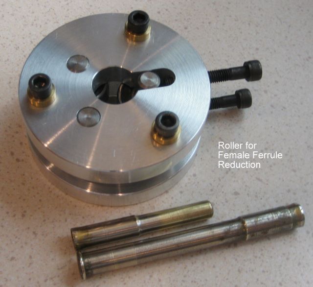
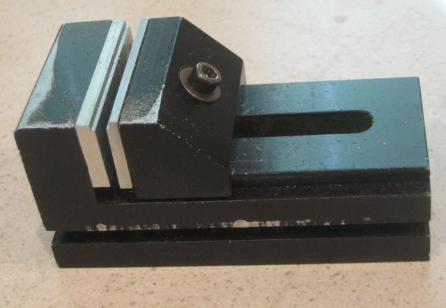
I have a small mill and lathe (Sherline). So I designed this tool as something that I could make with my limited resource. It is not like a tubing cutter; that approach seemed too complex.
I thought it would be a good idea to make the rollers as large as possible, in order to get the most hoop stress with the least contact stress. So I chose 7/8 inch diameter ball bearings to be the rollers. These will close down onto a diameter of .140 inch, small enough to do work on a “size 8” female ferrule.
To tighten down the rollers requires adjustment of two screws instead of just one; this is the price of simple construction. But I don’t think that it is a major disadvantage.

History

Once I understood that the tool did indeed work, I quizzed Jed some more to find its origin. Jed pointed to Dave Male, and Dave says that it is the idea of famed rodmaker Wes Jordan, during his time at Orvis. The original purpose was to flex a stuck ferrule set to help break it loose, but soon after it was found that female ferrules could be reduced. This origin is probably in the 1950’s.

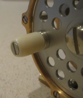
This picture, provided by Chris Bogart, is what I believe the older ferrule tools to be.

How to Use the Tool

Insert the ferrule and tighten the two radial screws equally, by feel of your wrist, and then turn the tool around the ferrule several times. Remove the tool and trial fit the ferrule set. Be quite careful at the start because if you go too far, you will end up having to re-lap the male ferrules. It is a trial-and error process, and I usually do not get permanent set of the female on the first two or three attempts.
Do not set the rollers on top of the moisture plug; that is a rigid point on the ferrule and cannot be spun down. It is the same with the welt. I stay back from these by 1/32 or 1/16 inch. The width of my rollers is 11/32 inch, so you may want to do separate rolls at two locations on the ferrule.
I have worked on both brass and nickel silver ferrules, and it took much more time to reduce the brass.

How to Make the Tool


I include these instructions for the benefit of home shop machinists with time on their hands, but I am also having several tools made to sell to guys who just want to get on with the main task of fixing ferrules.
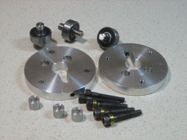
The parts are:
1. Three ball bearings, 7/8 OD by 5/16 bore by 11/32 wide. I chose double sealed bearings only because they were a little wider than other types.
2. Three short pieces of precision ground shaft, which will press fit into the bearings. Make proper press tools so that you do not press on the outer races of the bearings. Example material : McMaster-Carr 1327K73.
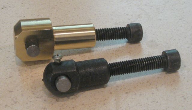
3. Five screws, 10-32 by 1.25 inch.
4. Three washers. I made thick ones to take up excess screw length, but you might decide to use standard washers and just make the plates thicker.
5. Three spacers 0.5 inch OD by .350 height and drilled to clear a #10 screw.
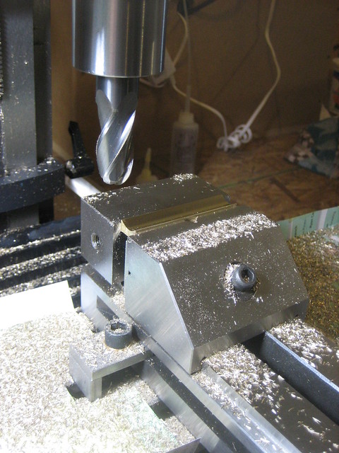
6. Two round side plates of aluminum alloy, machined per the drawing.

This drawing states no tolerances on the dimensions; rely on your common sense. The main problem is to ensure that the device can be assembled, and this requires precise alignment of two holes (5/16 diameter) and one slot (5/16 wide). To get this alignment, I screwed the two plates together and then made the 5/16 holes and slot.

(Article ends here)

Since writing this article, I have sold a number of tools by way of a classified ad on Clarke’s Forum. Email me if interested; my address is in the “About” section of this blog.

The batch manufactured tools are a little different from my prototype. The heads of the three axial screws are recessed in counterbores, and the five screws are 1 inch length instead of 1.25 .

Additional Information for Owners of the Tool

The fit of the dowel pins into the the bearings is a medium press. Do not attempt to remove or install bearings from the pins without proper press tooling; i.e., do not apply force to the outer races of the bearing because you will “Brinell” them.
The fit of the dowel pins into the aluminum end plates varies from light press to close clearance. If you remove the 3 axial screws, the assembly may or may not slide apart. In the latter case, you will have to “jack” the plates apart. To do this, first pull out the three spacers. Place the tool face plate (countersunk side) down on a bench. Thread the 3 screws into the back plate (tapped side). Cover the 3 bottom side clearance holes with pennies and evenly turn down the 3 screws, pushing the two plates apart.
If your tool has a light press fit of the 3 dowel pins, you may find, upon re-assembly, that one or two bearing outer races drag against the inside surface of one plate. Use an arbor press to center the bearing between the plates.

Update 12 Nov 2017:
The tool is not suitable for shrinking male ferrules because the tip end of the male will not roll down. Fix male ferrules in the usual way, by abrasion.
If your ferrules have been blued, the bluing will probably not survive rolling. Plan on re-doing the bluing.
There is no need to remove the ferrule from the rod while it is worked.
See also my earlier article:
Ferrule Shrinking
Also note that this blog has a page “Ferrule Shrinking” with ordering information.

Posted in Articles, Ferrules, Forming, Tools | 1 Comment

Acme Tandem Tap

This is a tap for cutting acme thread. It is of “tandem” configuration; the lead section cuts a triangular thread and the second section forms the trapezoidal acme profile.

I bought it because I have the scheme to make a CNC engraver for decoration of reels.

The thread size is 3/8-12. This is a “standard” acme thread for which taps are readily available. I have not searched for an acme die because I plan to use threaded rod for the screws.

Here I am tapping a trial block of Delrin, from which I will make anti-backlash nuts for the engraver. An anti-backlash nut is two plain nuts preloaded against each other by a spring. The 3/8 diameter is critical for me because it is the largest diameter that passes through the bore of my lathe spindle.

I also plan to make brass threaded-bore clamp-on shaft collars for the thrust bearings of the engraver leadscrews. The brass will be more difficult to tap, but an oversize pilot bore is suitable for a collar.

This is the trial nut on threaded rod.

The tap made clean threads and clearance can be felt in the 2G class fit.

Posted in Threading | Leave a comment

Fitting Reel Foot to Seat

This is my presentation for Grayrock 2015, on the fit of a reel foot to a reel seat. For an earlier post on this same topic, see 28 July 2014.

This presentation considers “cap and ring” seats like this, although many points carry over to other types of seat. It has only been in the last year that I have realized that this type of seat can work. Prior to that, I always bought rods with screw lock seats. I thought that my reel would fall into the river with any other type of seat.
Notice that the ring is tilted relative to the axis of the seat; this point will come up again later.

It should be no problem to get a good fit. After all, there is a drawing that defines the standard reel foot. But the drawing is flawed: it does not tell us the radius on the upper side of the foot. It doesn’t even tell us if that surface is a cylinder or a cone. From this flaw, problems can arise.
Because there is not radius specified for the top of the foot, any radius could be supplied and the part would still pass “first article” inspection by a QC department. Any claims by a reel seat manufacturer that their seats fit feet that conform to the AFFTA specification are nonsense, the “standard” fails to work as a standard. Just visualize a foot with a 5 inch top radius; I suspect it would not fit anyone’s reel seat.
When I first started making reels, I looked at the 0.35 bottom radius and the 0.04 foot tip thickness and decided that the top radius should be 0.39 . This worked OK on my rods, which all had screw lock reel seats. No reel customers reported problems until last year, and that problem was with a wood insert of 0.65 diameter. The ring (ID = 0.66) would not slide over my reel foot. We might guess that a deeper mortise would solve the problem, but the only good solution is a smaller radius on top of the foot. My next picture is a drawing that illustrates the geometry of foot contact with the insert and with the ring.

Consider the surfaces where the foot and seat meet. Here is a round insert, as you might have when there is a pocketed butt cap. If the insert diameter is too small (upper left) the reel will not be stable because it can rock on the seat. Fitting a ring is a problem. Take the dashed line to be the ID of the ring. As drawn, the ring fits the reel foot but not the insert. If we reduce the diameter to the point where the ring touches the insert, the ring will then only touch the foot at two points. Very likely, the foot will be scarred by the ring. The radius of the foot top should not be greater than the inner diameter of the ring.
An insert that is too large in diameter (upper right) is less of a problem because the reel is at least stable. But again, there are problems with the fit of the ring. You want a situation where the ring can touch the foot over broad area, not just at points. And it also should touch the wood insert over a broad area, or the wood may be scarred.
Mortising the insert (bottom two pictures) is a good solution because it allows the ring to make broad contact with both the foot and the insert. I like the milled mortise because it is a better support for the cap. But if the top of the foot has a larger radius than that of the ring, the two will still touch at only two points. That is why a deeper mortise would not be a good solution for my first “problem” reel foot.
On a mortised insert, the ID of the slide ring will be 0.010 or 0.015 larger than the OD of the insert. It is a good rule to make the foot top radius match the insert OD (i.e., OD/2). Then when the ring is pushed tight, it can flex a few thousandths into an oval shape. This provides a spring action that helps secure the reel foot. Now, when I don’t know what the insert diameter will be (the case most of the time), I make the foot top radius 0.35 . This fits the large number of commercial reel seats that are 0.69 to 0.72 diameter.
I am aware of reel seat inserts with diameter as small as 14 mm (0.55 inch). I do not know how to make a reel foot with a top radius that small; the foot tip would have knife edges at the corners. It must be that the bottom radius is smaller than 0.35 . (Update: A friend at the Grayrock meeting showed me a bench made reel from Australia, which is the continent the 14 mm reel seat insert comes from. It had a 0.35 inch bottom radius, but it was clearly much narrower than the AFFTA standard.)
If you order a reel from a home shop machinist, tell him the diameter of the of the reel seat insert that you prefer. You will get a better fit and a more secure reel.
If you buy complete reel seats, and reels from the fly shop, then take the reel seat to the fly shop and check fit before you buy the reel.
If you buy antique reels, then have the reel in hand before you make the reel seat.
Another issue has to do with spey rods. Before AFFTA, there was NAFTA, and their standard drawing specified two foot sizes. The spey foot had a bigger bottom radius as well as a few other slightly larger dimensions. AFFTA says to use the standard foot even for spey reels. But some large diameter “spey” seat hardware is still available.
I am convinced that the upper surface of the reel foot should be a cylinder instead of a cone. With a cone there is a varying radius and little chance of getting a good fit.

When making reel feet, I have been using a rotary table fixture to mill the cylindrical surface on the top of a foot. It might be possible to design a lathe mandrel to do this, but the milling fixture allows me to adjust the top radius.

Here is the milling fixture in use.

The cork checks, sliding rings, and caps for mortised inserts are simple lathe parts. I start with a piece of material that is long enough to make all three, and sequentially part off. With one chucking, I can turn the cork check, the ring, and the inside surfaces of the cap.

Turning the outside of the cap requires second chucking. I use an expanding mandrel. It has a tapered plug that expands the several fingers.

Here is the expanding mandrel in use.

The reel foot will be more secure in the cap if the opening of the cap has taper (7.5 degrees, the slope of the foot). And the ring will fit both the foot and the wood insert better if it has a 3.75 degree taper on one side.

The next several pictures are about making wood seat inserts. Here is the setup for drilling the blank. The essential lathe accessory is a 4 independent jaw chuck. I mark and center punch the end of the blank, and then use a center drill in the punch mark to hold the blank while tightening the chuck jaws.

Here I am turning the blank to round. I am using ordinary metal cutting bits for this, and would appreciate advice from any expert wood turners on a better tool.
Turning here is between centers, using a faceplate and dog.

I put these brass “inserts” into the ends of the wood insert while turning. The one at the headstock end has spurs to grip the wood.

Trimming to length can be done with a 3 jaw chuck. This should be done before the final diameter is cut, as the jaws will mark the wood.

To turn a mortise, you need a mandrel that holds the insert off center. Here is my mandrel for turning between centers.

And here is the mandrel in use.

Milling a mortise requires a mandrel that can be fastened to a rotary table. I do not have a center to support the free end of this mandrel, but the 5/16 rod seems rigid enough.

Here is the milling operation. Notice the .005 shim under one side of the mandrel base.

I like to make winding checks with a milled hexagon center. Before making the check, I first make a gauge so I can know when the hex is big enough.

Here is a complete hardware set for a rod, including Duronze ferrules.

Unrelated to the rest of the presentation is this final picture, a device for rolling female ferrules to a smaller inner diameter. Last year, Jed Dempsey attended this meeting, and he gave me the concept. I am in process of getting several made by a local machine shop, so see me if interested.

Posted in Foot, Presentations, Rods | 2 Comments

Sole of the Foot Revisited

In Sept 2011 I made a post on shaping the groove in the bottom of a reel foot. Part of the problem was that the groove radius needed to be about 0.35 inch, and the largest ball end mill that I could install on my Sherline mill was 0.375 inch (0.188 radius). So the answer was to “generate” the required radius by multiple passes of a smaller end mill: a certain depth at 0.125 off center, a little more depth at 0.100 off center, etc.

But now I have an “X2” size mill from Little Machine Shop, and it has an R8 collet system. R8 collets can be as large as 3/4 inch. So here is an 11/16 ball end mill and the groove (0.344 radius) it makes for the sole of the foot.

It took a lot of time to sand out the axial ridges on the generated arc. Now that is all behind me.

My advice to the aspiring reelmaker: You need both a lathe and a mill. These are very different tools. The Sherline mill, despite being one of the few American made tools you can buy, is too small for work on reels (even though I made more than 40 reels with mine). Milling requires a heavy and rigid tool, and a mill should be made from cast iron instead of aluminum.

The lathe is a different consideration. I am keeping my Sherline lathe because it allows me to work on parts up to 3 inch diameter. See the recent post on custom chuck jaws.

I turn reel parts with 4 types of work holder: 3 jaw chuck, 4 jaw (independent) chuck, faceplate, and ER-16 collet. The Sherline lathe lets me change these by just screwing on to the 3/4-16 spindle nose thread. The Chinese origin lathes from Little Machine Shop, Micromark, and others have a flange on the spindle. Work holders mount by studs and nuts, a time consuming installation.

Yes, I do wish that my Sherline lathe had more torque at low speed. The lathe stalls when I try to ream the female slide of a rod ferrule set. This might be cured by using a brushless motor drive.

Posted in Foot | 1 Comment

Screwless Vises

I do not know why these are called “screwless” because clearly there is a screw that pulls the jaws together. I believe that this is a good design because the angled screw pulls the held object down flat onto the vise base.

In the foreground here is Sherline’s 2 inch wide milling vise, weighing almost 1 pound. Behind is a 3 inch wide vise from Little Machine Shop, weighing almost 12 pounds.

I was motivated to write this post because I just finished making a new part for the LMS vise, the “nut”.

The original nut, in the foreground, is a bad design. It too easily rotates when you are adjusting the vise jaws and it has too little engagement with the clamping screw. You invest some time in aligning a vise when you clamp it to a mill table, and this time is wasted when you lose control of the nut. The new nut, which is made of some Duronze that was on hand, has much bigger flats so it cannot rotate while the vise is adjusted, and the engagement with the screw is 1/2 inch more than that of the original nut.

Sherline’s nut is one piece, and has a threaded through hole for long engagement of the screw and nut.

Sherline makes the vise base (and many other parts) by CNC milling of aluminum bar stock. The notches for the nut “pin” were made with a ball end mill, so the “pin” ends had to be rounded.

The pin on the LMS vise can be square ended because the notches are made by through drilling of the iron casting.

The seller of the first rotary table that I bought (auction site) was tardy in shipping. So to make amends he also sent a well used vise. I replaced its beat-up steel jaws with new ones of aluminum. Of course, I have since used this old vise to the near exclusion of the new one that I had bought with the mill.

Note the step in the vise jaws. This is quite convenient for holding many small objects.

Posted in Work Holding | Leave a comment

Custom Jaws

For my current line of bronze frame reels, the starting point for the front end ring, and for the rear end plate, is a disk sawn from the end of a 3 inch diameter bronze rod. This disk must be turned to remove the saw marks and to arrive at the correct thickness. But the “3 inch” chucks (both 3 and 4 jaw) of my Sherline lathe fall a little short of handling the 3 inch disk.

The chuck and disk cannot be spun, at least without using a riser block under the headstock: chuck jaws will strike the lathe bed. A 2.9 inch diameter disk would be OK. I don’t like to use a riser block; the tall tool post is less rigid and the tailstock then also needs a riser, and this is difficult to install.

There is a second problem with the chucks: the last step on the jaws is taller than the thickness that I want for the front end ring, or for the flange of the rear end plate. So far, I have dealt with these problems by
1. milling 4 shallow flats on the periphery of each disk and using a 4 jaw chuck (the flats fall in between the raised pillars), and
2. placing an .060 thick sheet metal spacer on the chuck jaws.
Point 1 is time consuming and point 2 probably makes it more difficult to produce a disc of uniform thickness.

So recently I bought Sherline part 11420, a second set of jaws for the 3 jaw chuck. These are like the original chuck jaws except they have not had steps machined in and they are unhardened steel so the user can configure them as desired. I have used them to make a set of jaws that are not as high (axial direction) and have less radial projection.

I milled out most of the waste material, then finished the jaws on the lathe. Here you see the jaws clamping a scrap material ring so that they are secure while being turned.

When you order these jaws, you send your chuck to Sherline so they can custom fit to the chuck slots.

So now I can surface the bronze disks with much less fuss.

Posted in Work Holding | 1 Comment