Way Covers

The Sherline lathe has leadscrews that are under the bed and cross-slide; these need no separate way covers. On the mill, the X and Z leadscrews are similarly protected, but the Y axis leadscrew is exposed to falling swarf.

For a long time I used an accordian fold set of covers. Mine were made from ordinary printer paper, without the glue-on end frames. They were reasonably successful; the paper was surprisingly springy.

Then I saw this set of covers offered by the Ebay seller “standarddesign910”. Just search for “Sherline way cover” and you should locate them.

The covers are sheet rubber and fasten to a frame that clamps around the saddle. I have used these covers for 2 years now and am quite satisfied.

Posted in Milling | Leave a comment

Minor Design Change

While making a second Fixed Spindle Reel of the smaller (3 wt) size, I increased the diameter of the lightening holes. (Modification on the right below.)

I believe that I like the larger holes a little better than those of the original.

Posted in My Reels | 1 Comment

Electrochemical Etching

This post documents another attempt to mark my reels. Here I have used an electrochemical etch kit from Lectroetch. They promote its use to knifemakers, where the blades are typically steel.

The kit consists of a low voltage AC transformer with pad and alligator clip electrodes, bottles of etching electrolyte and neutralizer, and some stencil material.

The stencil material is a laminate of permeable and impermeable layers. The impermeable layer can be rubbed away with a stylus. It can also be removed using a mechanical typewriter (remember those?). Below are stencils that Lectroetch made for me.

This is my fixture. I am etching the oversize head of a nickel silver screw, which threads into the center hole. A small groove at one corner is a grip point for the alligator clip.

Here I am ready to etch. The stencil is secured in position over the screw head.

After etching with the wetted electrode pad, I had a black image. But when I wiped it with the neutralizer, most of the black oxide came away.

I sent a nickel silver sample to Lectroetch, and they confirmed that the oxide does not adhere on this material. So it looks as if I can get an untinted etch, if I can figure out a way to remove the rest of the oxide without defacing the image.

I later tried etching some 303 stainless, and the black oxide adhered.

One problem with the etch on both nickel silver and on stainless is that it is quite shallow. The logo is quickly obscured by a little sanding at 1200 grit. I think that the engraving done by a jeweler, even by diamond point drag, is more durable.

Posted in Engraving/Marking | 2 Comments

Tap for Aluminum

The frame screws of my reels are 4-40 UNC. There are 10 such holes (foot & pillars) to tap for each reel. On repetitive tasks, it is good to have the best possible tool. McMaster-Carr sells “Vanadium Steel Hand Taps for Aluminum” which I have used for several months.

The threaded length on this 4-40 tap is just 0.3 inch; behind that is a reduced diameter shank so that a deeper hole may be tapped.

Here I am tapping a reel foot of 7075 aluminum. This operation proceeds with much less effort (i.e., back and forth working) than is required by the typical hardware store tap.

Note 7 Jan 2020: It did not last. I think that this is only the second tap that I have broken since I started reel making.

Posted in Threading | Leave a comment

Engraving with the Mill

In the previous post I showed the artwork for a logo in the form of a circular monogram. This is meant for use in electrochemical etching. After making this artwork, it occurred to me that it might be simplified to the point where it could be engraved using just my vertical mill and its rotary table.

So here is my attempt at engraving with the mill. This is a 5/8 inch diameter brass slug that represents the head of the rear spindle screw of my reel. It has been engraved with a 1/16 inch diameter square end mill. The depth of the engraving is 0.005 inch. When I have taken parts to jewelers to be engraved, the depth is about 0.001 inch.

The final appearance would be enhanced if the bottom of the groove were burnished with an appropriate tool.

I am still working on electrochemical etch and will save this as a fall-back process if that proves unsatisfactory.

Update 3 Dec 2012: Here I have filled the milled grooves with paint

Posted in Engraving/Marking | 2 Comments

Logo

This is another post on the problem of marking my reels. In the spirit of “divide and conquer”, I have decided to put just the initials “NB” on the external screw head, and the sequence number somewhere inside the reel, perhaps with stamps.

Having the same “NB” on every reel lets me consider electrochemical etching, which I expect will make a dark impression. Also, I can make a real logo rather than just a couple of standard text characters. So here is my artwork, for which I am seeking a stencil.

My tool for making this was Microsoft Paint. Had to do careful arithmetic on pixel numbers, and delicate positioning of the mouse.

Posted in Engraving/Marking | 2 Comments

Number Punches

This post is about another attempt to make identification marks on my reels. Number punches are often used to mark a serial number on equipment nameplates. The resulting characters are usually readable but not very neat; the punch is not accurately placed, it is hit too hard, etc. Is it possible to make neat letting with punches if the are accurately placed and guided to be normal to the surface punched? My conclusion is that it still does not produce neat lettering.

Here are the parts that I made to serve as a punch guide: a base to hold the target screw, a spacer, and a guide for the punch.

By rotating and/or flipping the guide, four character positions are realized.

This is the punch assembled for the first character position.

Here I have made all four characters, using a hammer. The “N” and “2” are deeper than the other characters.

My fixture positions the punch well enough that I can go back and hit a second time, but I was unable to improve the result.

Here I used an arbor press to make the impressions.

The right side of the “N” is not deep enough, and alignment is not very good.

So I will resort again to an engraving service.

Update 18 Jan 2013: Here, I believe, is the proper use of the punches: add serial number to an inside, hidden surface. I may settle on this and forego external marking that must be done at high quality.

Note that the “1” here is a deeper impression than the other characters. It has a smaller total line length, and should therefore receive a lighter tap from the hammer.

Posted in Engraving/Marking | Leave a comment

Edinburgh Etch

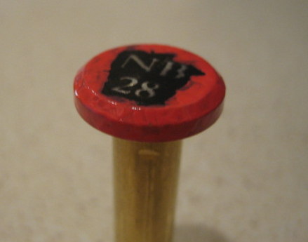
I like to put some identifying marks on my reels, typically the letters “NB” (for North Branch) and a two digit sequence number. In the past, I have taken a group of rear bearing caps to a jeweler’s shop and had them engraved. The local jewelers have machines that push a stylus across the surface of the metal, making a rather light scratch. A rotary engraver would make a better impression. I made a bracket to hold my Dremel tool on my mill (this blog, 14 Aug 2011). This lets me carve straight lines and circular arcs, but is not sufficient to do lettering. Making a pantograph that is large enough to hold the Dremel is too big a project for the value realized. One can buy rotary engravers, but they are expensive.

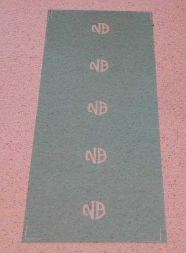
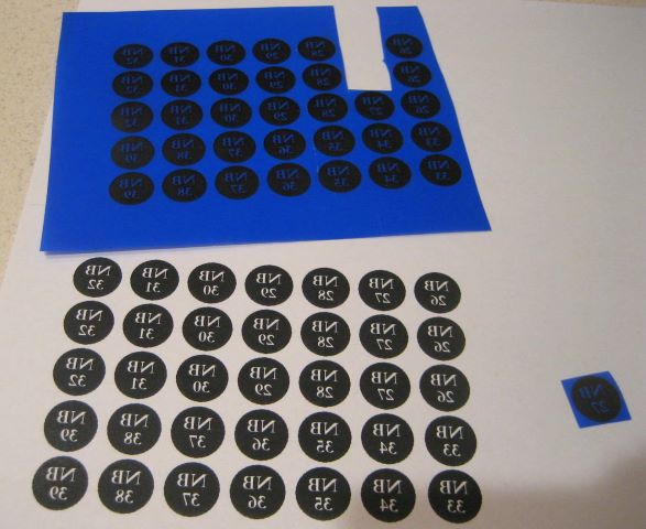
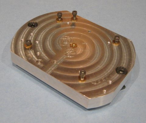
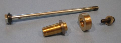
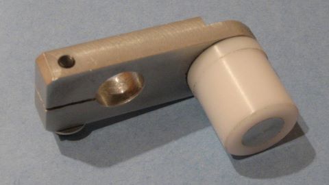
So I have been thinking about etching to create the letters and numbers. On my new reel model, these go onto the head of a large screw that secures the spindle to the reel backplate. The area to be engraved is a circle of about one half inch diameter, so the four characters need to be about 1/8 inch tall. As best I can determine, the preferred etchant is Edinburgh Etch, a mixture of ferric chloride and citric acid. To make a mask, I bought some fine point “opaque paint markers” meant for calligraphy, but could not form characters small enough. So my experiments here are with Press-n-Peel, a medium used for DIY circuit boards. Below is my artwork, and the copy made on Press-n-Peel.

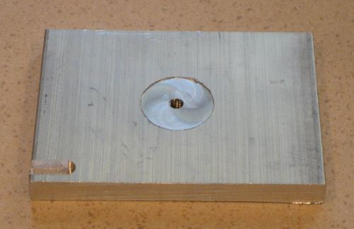
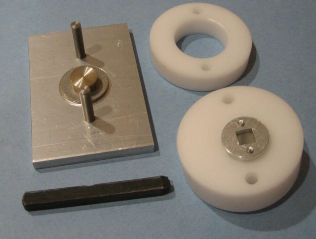
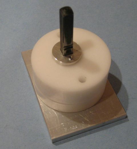
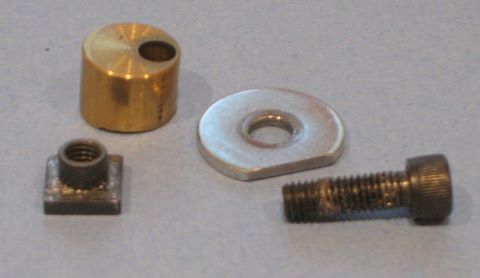
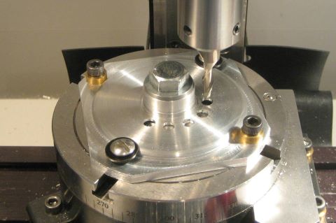
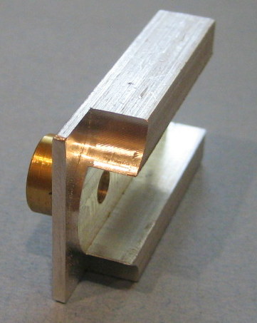
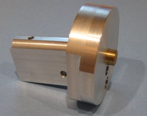
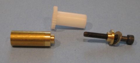
For a heat source, I borrowed a craft iron and made a bronze disk to hold the screw while it warmed up. The disk has a hole on its outer diameter where I can insert an oven temperature probe.

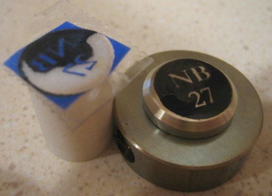
The iron had enough power to get the screw above 300 deg F. But I had trouble getting complete transfer of the mask. Here you can see a poorly transferred mask and the piece of Teflon that I used to apply pressure on the hot screw head.

It was difficult to hold the Press-n-Peel in the exact position while pressing. If I make additional trials with this method, I will make some type of mechanical clamp that I can assemble cold, then put the whole thing into an oven.

After getting a somewhat satisfactory transfer, I covered the edges of the screw head with paint.

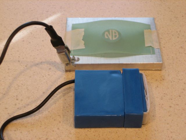
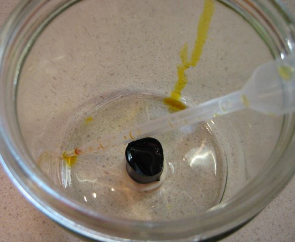
Here is the etching process, using electrical tape to make a dam to contain the etchant.

The instructions that I had said to etch for 20 to 60 minutes, depending on the newness of the acid. I etched for 30 minutes.

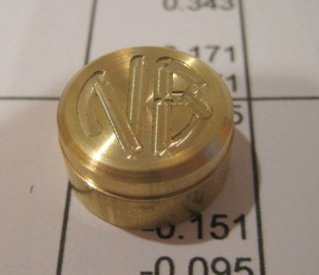
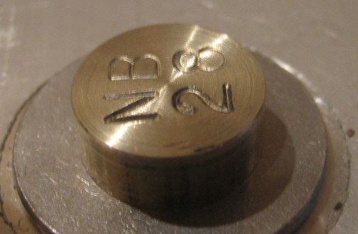
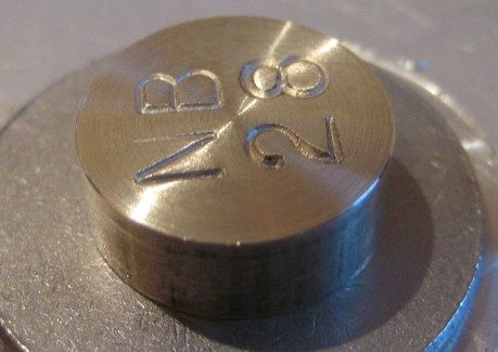
But the result was an insufficient impression, plus gouges where I did not adequately cover with paint.

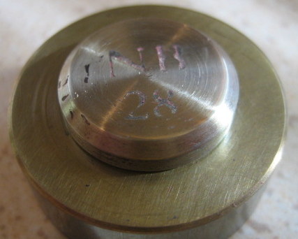
It looks as if the etchant is strong enough; the “gouges” at the paint gaps show good etching. I think that the problem is the Press-n-Peel mask. It looks as if the characters are unmasked, but something has partly blocked the etching there.
The effort so far is unsuccessful. I post this as information for anyone who may work on a similar approach.

Update 6 Nov 2012:
In the replies to this post, Rich has suggested hand engraving. This has caused me to buy a book, The Jewelry Engravers Manual. I recommend this book to anyone who has interest in this dying craft. It explains gravers and sharpening, and how to cut several type of letters. Last week a jeweler told me that hand engraving is the only way to get a deep impression, but that he knew no one still offering it as a service. This book will sit on my shelf as another technical reference on a subject that I will never pursue.

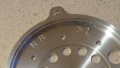
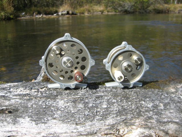
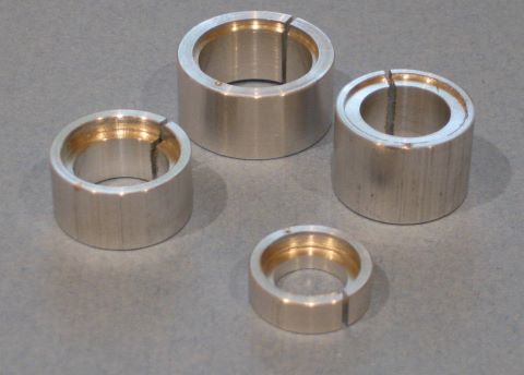
I did go to an engraver and have several parts done.

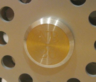
He did a good job, but as with previous machine engravings, the impression is not very bold. He told me that the engraving would not look very neat if done more deeply. I have dealt with four different jewelers on this matter, and the result is consistent: machine engraving can produce only a faint impression.

For a while I watched the Ebay auctions for pantograph machines. These go for $400 to $750 (with motorized spindle) and a font set is more than $100. To me, this is too much for a machine that only does one thing.

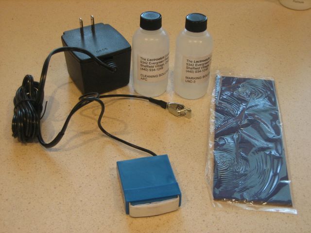
Leroy’s suggestion about electrochemical engraving has since become my interest. From what I see, this process causes a darkening of the etched area (why?) which gives contrast even though the etch may not be deep. A $60 machine is certainly in my ballpark. So I am going to pursue this option. My stencil will just be the letters “NB”, and I will stamp or otherwise mark the sequence number on an inside, hidden area of the reel.

Posted in Engraving/Marking | 5 Comments

Plan Set for Fixed Spindle Reel

Soon available at The Eclectic Angler is my new plan set for two sizes of the Fixed Spindle Reel.

Update 27 Nov 2014: Sales of this plan set have been moved from The Eclectic Angler to Reel Lines Press.

The set includes 24 drawings, 12 pages of construction notes, and 2 tables listing raw materials. Examples below.

As errata are discovered, I will make updates to this post.

6 Nov 2012: Started a size B reel this morning and right away found an error. Page 5 of the step-by-step, step 2 should be “2.4 by 2.5 inches”. (It’s hard to get 2.6 inches from 2.5 inch bar stock.) Same problem on page 7.

23 Nov 2012: The design incorporates two off-the-shelf screws, 4-40 FH to secure the counterweight and knob pin. I bought screws with a straight slot, and found that they have a burr at each end of the slot which will prevent them from pulling down properly into the countersink. Fix by filing.

24 Nov 2012: Drawing 1052, reference dimension 0.65 should be 0.065

27 Nov 2012: Step-by-step instructions for Front Spool End and Rear Spool End, pages 9 and 10. For step 18, make the spacer plate from aluminum instead of acetal. Acetal is too slick. The spool end is clamped to the rotary table by a central bolt, and acetal may allow the plate to rotate when it is first touched by a plunging end mill.

4 Dec 2012: For the smaller (B) reel, drawings 1039, 1047, and 1049 call out 0.313 inch diameter lightening holes. I think it is better to make these 0.375 diameter. You can see a comparison at the blog posting of 4 Dec 2012.

20 Feb 2013: Drawing 1057 depicts the forming of the wire spring. The distance between centers of two phantom circles is 1.40 inch. These two circles should be .188 inch diameter, fitting the groove diameter of the two spring pins.

10 April 2013: Drawing 1051 calls for a slot width of .032 in the knob pin. This slot should be a little wider for better fit of common screw driver blades, say .040 inch.

24 June 2013: Drawing 1053 says “Use any involute cutter (1-8)”, but I now think that it would be best to select cutter #4 or #5. If you use a cutter meant for a smaller number of teeth, you will likely reduce the OD of your ratchet.

Posted in My Reels, Plans | Leave a comment

Fixtures for the Fixed Spindle Reel

These are the fixtures and modified tools that I use to make the Fixed Pillar Reel. Like yesterday’s post , this one supports an upcoming plan set. There is nothing new here, I have just brought it all together in one post.

To release collets and othe Morse tapers from either headstock spindle, keep shaft collars on the spindle extensions. Then push the loosened bolt with the “gear puller”.

This clamp lets me use the 4 jaw chuck as a milling vise.

These indicators have home made fixtures for centering on the lathe and rotary table.

Spacer plates for chucks and face plates create clearance for cutting tools.

This mill toolplate holds a Front End Ring or Rear End Plate. It has a pilot pin for the rotary table.

This is a lathe faceplate for the Front End Ring or Rear End Plate.

This clamp holds a spool end plate down on the rotary table.

This clamp holds a spool end plate against a lathe faceplate. The brass part has a Morse taper.

These support plates protect the rotary table from plunging end mills when spool end plates are perforated.

Note 27 Nov 2012: The plates shown are Delrin, but I am re-making them from aluminum. Delrin is too slick and may allow the spool end plate to rotate around the central clamping bolt.
Here is the aluminum plate in use. It has two bolts the clamp it to the rotary table, and two pan head screws that supplement the clamping force of the central bolt.

This 0.500 reamer has its shank turned down to fit a 3/8 chuck. The wrench gives the tailstock chuck extra torque capacity. Here is an example of pushing the Sherline lathe a little past its design capability.

I put aluminum jaws on this old milling vise. The rabbet holds bar stock parallel to mill spindle travel.

This is the “toenail clipper” that shapes the end of the foot. It pilots on the rotary table.

This sanding mandrel for the foot sole is held by a 3 jaw chuck and live center.

This fixture is for shaping the top of the foot.

Here are several pot chucks.

These are Delrin rings. The split one holds the bushing while it is reamed. The larger one pads the chuck jaws (4 jaw) while holding the spool hub.

This clamp holds the ratchet/bushing while teeth are cut.

Here is a gear cutter in a brass mandrel.

This fixture helps shape the pawl.

A bonding fixture ensures that spool end plates set squarely on the spool hub.

These wrenches install the spindle.

A crank makes screw cutting with dies easier. Sherline sells a crank as part of their (single point) screw cutting attachment, but this smaller crank fits the lathe spindle extension without removing the motor.

Posted in Alignment, Fixtures, Tools, Work Holding | Leave a comment