
My CNC engraver has progressed to the point that it is ready to use. Before buying design software, I decided to try hand coding a G code program.
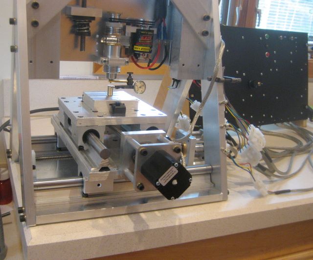
The task here will be to mill the complex perimeter profile of the rear end plate (or front end ring) of a raised pillar reel. The blank will be screwed to an aluminum tooling block that is clamped to the X-Y stage.
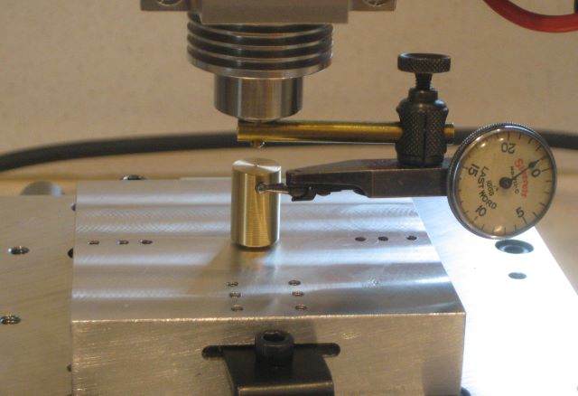
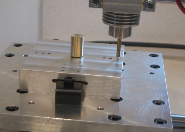
To align the block, I have made a brass pin that goes through the block and screws into a tapped hole in the stage. A test indicator mounted to the milling spindle show total runout.
I did not buy stepper motors with double shaft extension, which would allow manual cranks for axis zero adjustment. But I find it reasonably easy to turn the screws by gripping the acme shaft collars on the thrust assembly.
Once the spindle is centered, I can move (under CNC control) to one of the mounting holes and hold a tapered pin in the spindle to get angular alighnment.
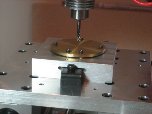
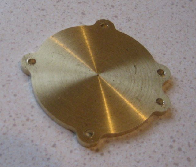
Here a blank is screwed to the tooling block. This small blank is the waste material from making a front end ring.
To create a G code program for the outer profile, I set up an Excel spreadsheet that calculates the end points of the 20 arcs that define the profile. The top section of the spreadsheet does the calculations, and the lower part organizes the X and Y coordinates into a table that can be read as G code.
And here is the profile milled into the blank. It is not perfect; there is a visible cusp at each point where the base circle meets a fillet at each side of a lag. I was able to trace this problem to an error in the Excel spreadsheet.
To turn the spreadsheet into a G code program, I export it as a “formatted text (space delimited)”, which has extension .prn . After editing out the calculations in the top part of the file and changing the extension to .txt, the file is ready for use by a G code interpreter.
Note 3 Jan 2020: The main intended use of the CNC machine was engraving. This post shows that the intricate outline of a raised pillar end plate could also be profiled, perhaps saving much time of manual mill operation. However, I have continued to do the profile manually. As you will see in an upcoming post, I had a lot of trouble with cutters working loose from the spindle chuck. This traumatic experience discouraged further work with “heavy” milling cuts.

Hi Dave,
I build CNC machines for a living (not a good one :)). Your machine looks great and I am sure you will get good results from it.
For lining up the tooling blocks you could place some dowel pins on two adjacent sides of the block. Two per side. I used 8mm pins and the holes where drilled with a precision reamer.This way you just place the block in the corner and lock it up tight. I then probe the edges to find the center of the block and all my programs run from that center point as reference. Once you know the offset of the block you just store that position and never have to measure again.
Before you buy any CAM software, have a look at Fusion360. It is cloud based but free and very powerful.
Marius,
The problem that I have with probing the edges of the block is that the diameter of my edge finder is 3/8 inch and the WW collets that fit my spindle chuck cannot be that big. I made the brass bracket for the test indicator with a 1/8 inch diameter shank.
If I understand your use of dowel pins, these would fit into the “stage” of my engraver, and the tooling block then slides into position against them. Yes, that sounds like a good idea.
Something that I have yet to learn is whether I can run the X,Y axes into the limit switches and from there move to the stage center accurately. Since I was unsure that the repeatability would be good, I opted for the test indicator.
As I sat down here to read your comment, I received a telephone call from a friend here in the US who saw the post and also recommends Fusion 360.
Dave
Dave
If you use good quality switches the repeatability could be as good as 0.001 mm and better. The pins are removable with some patience as they form a airtight seal when you used a reamer drill. I put mine in and leave overnight and by the morning they have dropped all the way down. I will send a picture if you want?
Marius,
I don’t think that I need a picture of the pin installation, I believe that I can visualize. Since the holes would be made in my stage plate which is only 0.5 inch thick, I could easily add an air bleed hole through to the bottom side.
What puzzles me, however, is “reamer drill”. Is it like any of these?
http://www.mcmaster.com/#reamers
Dave
Yes exactly that. You drill the hole undersized by 0.3mm and then you finish it with the reamer. For 8mm pins I used a 7.8mm precision drill bit and then reamed to 8mm.