Anodized coatings can be dyed, but I prefer the process of electrolytic coloring; it is easier to get a uniform finish. My earlier post on coloring was on 24 Aug 2012.
When growing the anodize layer, the design of the cathode is not critical because the resistance of the cell is almost entirely in the barrier layer of the coating itself. This guarantees a uniform coating. The electrolyte is about 18% sulfuric acid and so is highly conductive. But the electrolyte for coloring is only about 2% acid, and so is much less conductive. The counter-electrodes (coloring is done with an AC supply) have to be arranged to create a uniform electric field over the surface of the work.
How careful do we have to be with counter-electrode design? Software is available for 3D mapping of electrostatic fields, but the effort required is excessive. I have instead relied on trial and error, and have been lucky.
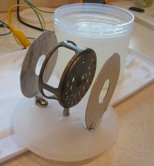
I do coloring in a 24 ounce plastic jar, and suspend the electrodes from a homemade cover. To color the spool side plates of an earlier reel design, I made the simple counter-electrodes shown below.
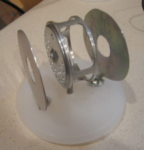
Here I am preparing to use them on a one piece frame.
And the result is satisfactory, the coloring is uniform.