
I have had a MiniLathe for several months now, but am still having trouble making it function well enough to replace my Sherline lathe for routine reel making operations. One particular problem is that the dial of the compound slide will slip relative to its acme screw, thus losing my zero reference for an axial direction cut.
To understand the design flaw that lets this happen, we have to examine the parts of the slide drive screw.

Front to back here are
– clamp screw and lock washer
– crank
– washer
– dial and its loading spring
– screw guide
– acme screw
Notice on the acme screw the largest diameter portion (only about 1/8 inch axial length) which I will call the thrust collar.
The cross slide drive, which does not have the dial slip problem, has a similar acme screw with thrust collar. Its thrust collar is trapped between two parts of the apron assembly and thereby takes thrust reactions for both tension and compression of the screw. But the thrust collar of the compound screw is not trapped. The collar takes the thrust reaction (against the back of the screw guide) when the screw is in compression. But when the screw is in tension (as it is whenever the compound slide is advanced) the thrust reaction passes through the washer and the dial onto the guide plate.
The dial is subject to three sources of frictional torque:
– from its loading spring
– from the washer
– from the guide block
The problem with this is that the friction from the guide block can overcome the other two frictional torques. When this happens, the dial slips in angular position relative to the acme screw. This is a disaster for someone like me who depends on the dials. It would be much better if the the thrust collar was trapped so that the dial was not exposed to axial thrust.
So here is the part that I made to trap the thrust collar of the compound acme screw.
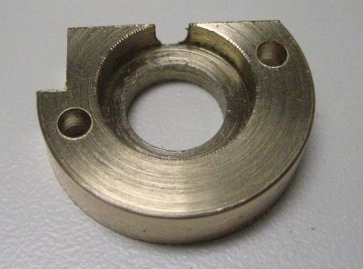
The flat on the top provides clearance from the bottom of the slide, and the notch at the left clears the gib.
This part screws to the back side of the guide block.

The axial travel of my compound is now reduced by about 1/4 inch, but this is a small price to pay for a dial that actually works.
For adjusting the MiniLathe, see the 3 videos “Cross Slide & Compound” on this Youtube channel:
https://www.youtube.com/results?q=frank+hoose+mini+lathe&sp=SADqAwA%253D
My efforts to adjust the cross slide and compound gibs were relative ineffective until I lapped the slide dovetails. My lapping procedure:
1. Remove all the parts shown in the top photo of this post.
2. Slather valve grinding compound (500 grit) on the dovetail and gib surfaces.
3. Manually push the engaged slide back and forth several dozen times.
4. Clean off the grinding compound (now contaminated with metal).
5. Repeat steps 2, 3, 4 several times.
